G10 Hardware Maintenance Guide 7.13.2 51
3
Blades and RTMs
Rev. 002-140228
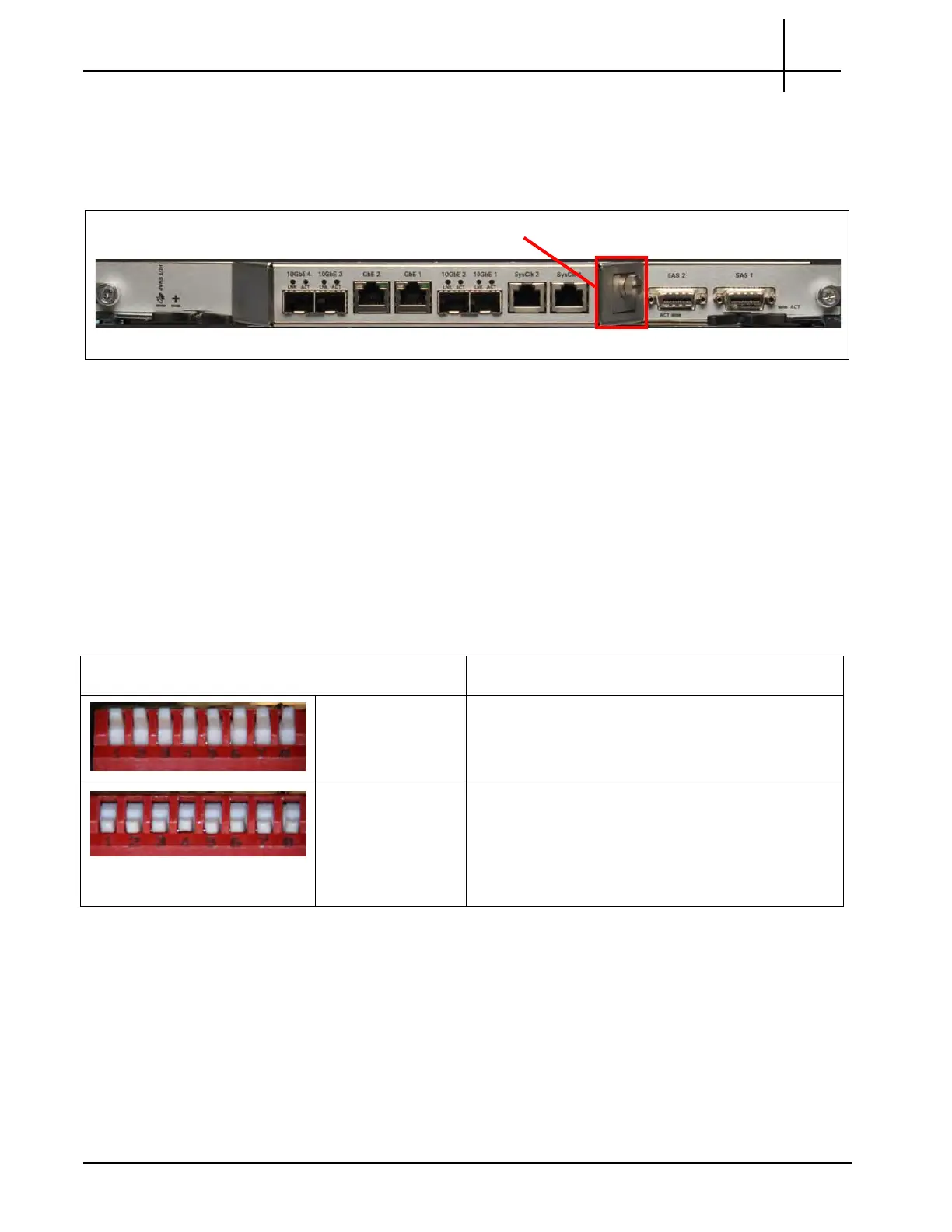
SysClk Termination Switch
Some G10 probe configurations require the use
of the SYSCLK 1 and SYSCLK 2
connectors, and you must change settings on the SYSCLK Termination switch. The
TRM100 provides access to the SYSCLK termination switch behind a faceplate
(Figure 3.22).
Figure 3.22 - TRM100 SYSCLK Termination Switch
Y
ou need to set the SYSCLK DIP switch settings in the following
scenarios:
G10 standalone chassis using external SYSCLK—determine if the SYSCLK signal is
terminated or bridged at customer site and set the DIP switches accordingly.
Media probe two-chassis configuration—the Primary and Expansion Chassis must
use the TERMINATED setting on ALL THREE SYSCLK Termination Switches.
Table 3.13 shows the SYSCLK Dip Switch Settings. All eight DIP swi
tches must be set to the
same setting at any given time; all switches must be se
t to the up position or all switches must
be set to the down position.
SYSCLK Termination
Switch
Table 3.13 - SYSCLK Termination Switch Dip Switch Settings
Setting Description
Up (open/off)
BRIDGED
SYSCLK is BRIDGED (not terminated). This is
the
de
fault switch setting.
Down (closed/on)
TERMINATED
SYSCLK is TERMINATED with a 200 Ω pu
ll-down
resistor.
ALL TRM10
0
RTM SYSCLK switches on the Media
Probe Primary and Expansion chassis must use this
setting.
Tektronix Communications | For Licensed Users | Unauthorized Duplication and Distribution Prohibited

 Loading...