G10 Hardware Maintenance Guide 7.13.2 29
2
Chassis Subsystem
Rev. 002-140228
Table 2.3 displays the AC PEM LED indicators.
FAN TRAYS
The Chassis subsystem supports two fan trays in a push/pull configuration:
One fan tray is accessible from the front of the chassis and contains the replaceable
air filter.
The other fan tray is located in the rear of the chassis.
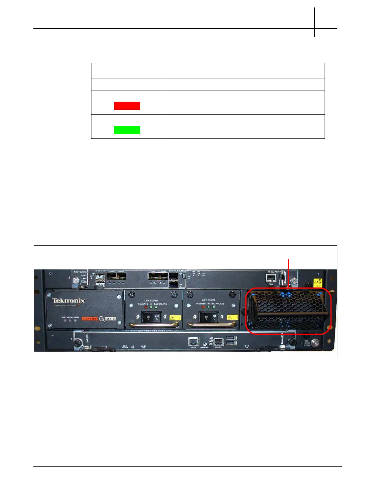
Figure 2.7 displays the front fan tray. Refer to Replacing the Fan Tray and Replacing G10
Chassis Air Filters for replacement details.
Figure 2.7 - Front Fan Tray
Table 2.4 - AC PEM LED Indicators
LED Color Description
OFF Power is disconnected.
RED Power supply is in a failed state.
GREEN The power is connected correctly.
Tektronix Communications | For Licensed Users | Unauthorized Duplication and Distribution Prohibited

 Loading...