G10 Hardware Maintenance Guide 7.13.2 18
1
G10 Probe Overview
Rev. 002-140228
G10 MEDIA PROBE CONFIGURATION
To support RTP monitoring, Tektronix also provides a multiprobe configuration called the G10
Media Probe. The G10 Media probe consists of two G10 chassis with the supported
configurations listed in Table 1.3. See Figure 1.5 and Figure 1.6 for a graphical view of the
media probe configuration.
The IICs within a multiprobe configuration must be the same model, either IIC100 or
IIC200. You cannot install mix IIC100s and IIC200s within the same multiprobe
configuration.
For details about the components of the media probe, refer to the appropriate sections in this
guide. For information about installing and cabling the media probe, refer to the G10 Media
Installation Guide.
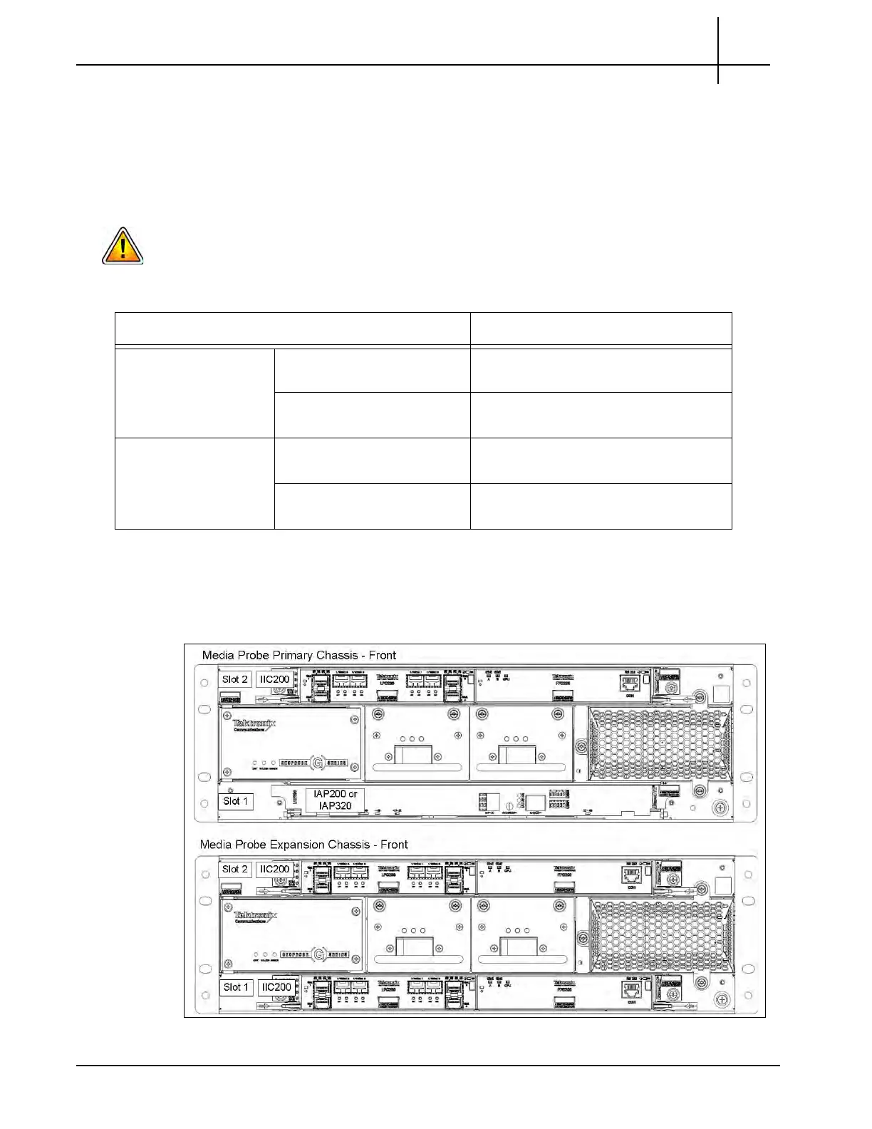
Figure 1.5 shows the front view of the G10 media probe components (IIC200 version).
Figure 1.5 - G10 Media Probe Front
Table 1.3 - G10 Media Probe Configurations
Chassis Supported Blades
Primary Chassis Slot 1 (Bottom) IAP200 + PRM200 RTM OR
IAP320 + PRM300 RTM
Slot 2 (Top) IIC200 + SRM200 RTM OR
IIC100 + TRM100 RTM
Expansion Chassis Slot 1 (Bottom) IIC200 + SRM200 RTM OR
IIC100 + TRM100 RTM
Slot 2 (Top) IIC200 + SRM200 RTM OR
IIC100 + TRM100 RTM
Tektronix Communications | For Licensed Users | Unauthorized Duplication and Distribution Prohibited

 Loading...