G10 Hardware Maintenance Guide 7.13.2 55
3
Blades and RTMs
Rev. 002-140228
IAP320
IAP320 LEDs
The IAP320 indicators provide status and error information. The LED indicators are located on
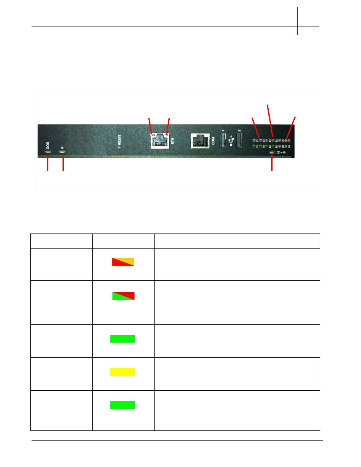
the front panel of the board. Figure 3.25 displays the front panel LEDs of the IAP320.
Figure 3.25 - IAP320 Front Panel LEDs
Table 3.16 displays the IAP320 LED indicators.
OOS +
F1-F2
H/S
ETH
Link
ETH
Activity
B1-B2
U1-U4
Table 3.16 - IAP320 LED Indicators
LED LED Color Description
OOS RED or AMBER Indicates out of service status.
RED or AMBER—The CPM is out of service.
OFF—Normal operation.
Health (+) GREEN or RED Indicates the health of the RTM.
GREEN—No errors.
RED—An error occurred.
OFF—The board is not powered on.
ETH Link LED GREEN
Indicates status of Ethernet connector.
GREEN—The link is available.
OFF—No link established.
ETH Activity LED YELLOW
Indicates the status of Ethernet traffic on the connection.
YELLOW—Ethernet activity occurring.
OFF—No Ethernet activity occurring.
F1-F2 (L) GREEN
Fabric Interface Link Indicator
GREEN = The Ethernet link is up.
OFF = No link established.
Tektronix Communications | For Licensed Users | Unauthorized Duplication and Distribution Prohibited

 Loading...