G10 Hardware Maintenance Guide 7.13.2 66
3
Blades and RTMs
Rev. 002-140228
SAS AMC
The SAS AMC on the IAP100 provides connectivity to the disk array via two SAS connectors.
Figure 3.35 displays the SAS AMC. Refer to SAS AMC (IAP100) for removal/replacement
procedures.
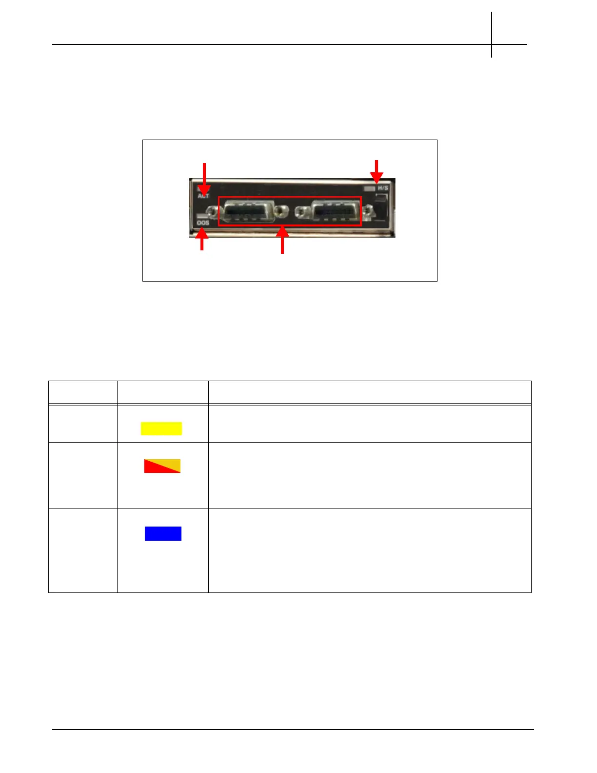
Figure 3.35 - IAP100 SAS AMC Connectors
SAS AMC LEDs
Table 3.24 displays the SAS AMC LED indicators.
SAS AMC Connectors
The SAS AMC contains SAS Port 1 and SAS Port 2 that provide connectivity to the storage
enclosures.
SAS Connectors
ACT LED
OOS LED
Hot Swap LED
Table 3.24 - SAS AMC LEDs
LED LED Color Description
ACT YELLOW YELLOW—SAS activity on the device.
OOS RED or AMBER Indicates the device is out of service
an
d is controlled by the IPMC. Valid
options are:
RED or AMBER—The CPM is out of service.
OFF—Normal operation.
H/S BLUE Indicates when it is safe to remo
ve the module. Valid options are:
BLUE—The module is in standby mode and can be safely extracted.
OFF—The module is operational, and it is unsafe to extract it.
BLINKING—The module is in a transition between standby mode
and operational mode.
Tektronix Communications | For Licensed Users | Unauthorized Duplication and Distribution Prohibited

 Loading...