G10 Hardware Maintenance Guide 7.13.2 46
3
Blades and RTMs
Rev. 002-140228
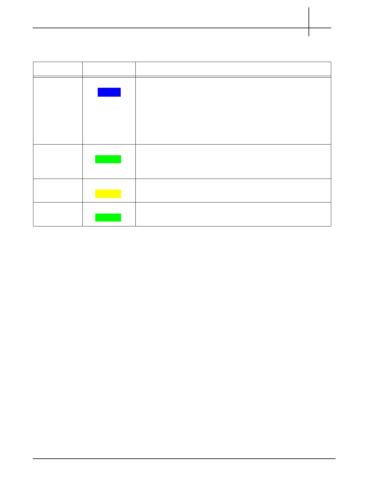
Table 3.8 describes the LPC100 AMC LEDs.
IIC100 RTMs
The IIC100 supports the following RTM configuration options for deployment:
8x1G probe—IIC100 and the SRM100 RTM
Mixed 1G and 10G probe—IIC100 and the TRM100 RTM
SRM100 RTM
The SRM100 RTM is used in 8X1G installations and connects to the back of the GeoProbe
G10 chassis in the upper slot location. It performs the following functions (Figure 3.17):
Communicates the board’s health and configuration status to the IIC100
Provides two Gigabit Ethernet links for connectivity to second controller enclosure
Sends and receives data to the disk array storage subsystem
Table 3.8 - LPC100 AMC LEDs
LED LED Color Description
Hot Swap BLUE Hot Swap Indicator which indicates when it is safe to remove the
modu
le.
SOLID BLUE—The module is in standby mode and can be safely
extracted.
Off—The module is operational, and it is unsafe to extract it.
BLINKING BLUE—The module is in transition between standby
mode and operational mode.
+ GREEN Indicates the health of the device.
GREEN—No errors.
OFF—Out of service.
ACT YELLOW GbE Port Activity Status Indicator
YELLOW = Activity.
LNK GREEN GbE Port Link Status Indicator
GREEN = The link is up.
Tektronix Communications | For Licensed Users | Unauthorized Duplication and Distribution Prohibited

 Loading...