G10 Hardware Maintenance Guide 7.13.2 47
3
Blades and RTMs
Rev. 002-140228
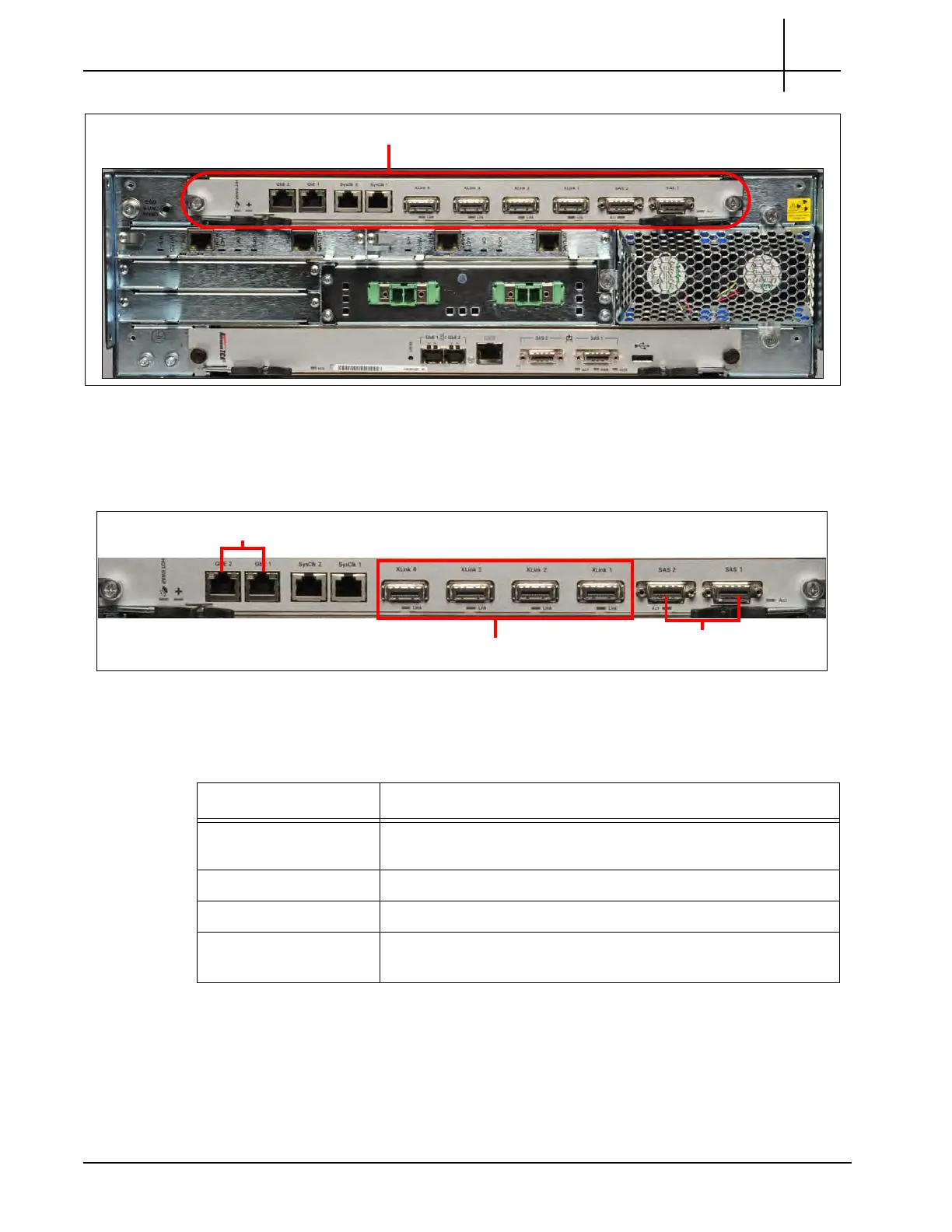
Figure 3.17 - SRM100 RTM
SRM100 RTM Connectors
Figure 3.18 displays the SRM100 RTM connectors.
Figure 3.18 - SRM100 RTM Connectors
Table 3.9 describes the SRM100 RTM connectors.
GbE1 and GbE2
XLink 1-4 (not used)
SAS Connectors
Table 3.9 - SRM100 RTM Connectors
Connector Description
GbE1–GbE 2 These connectors are the RJ-45 Gigabit Ethernet connectors to
th
e s
econd controller enclosure.
SysClk 1–2 These connectors are not used.
XLink 1–4 These connectors are not used.
SAS 1–2 This connector provides connectivity to the ex
ternal disk array
storage system.
Tektronix Communications | For Licensed Users | Unauthorized Duplication and Distribution Prohibited

 Loading...