G10 Hardware Maintenance Guide 7.13.2 64
3
Blades and RTMs
Rev. 002-140228
IAP100 LEDs
The IAP100 indicators provide status and error information. The LED indicators are located on
the front panel of the board (Figure 3.33).
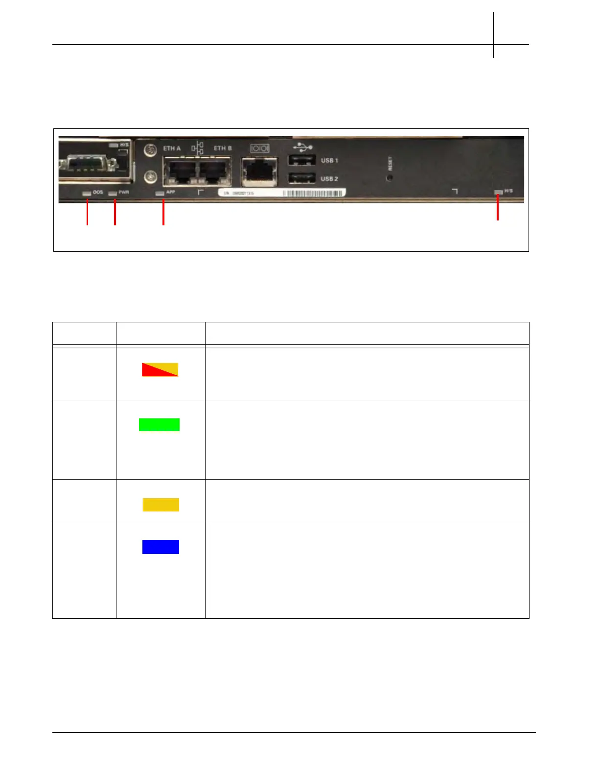
Figure 3.33 - IAP100 Front Panel LEDs
Table 3.22 displays the IAP100 LED indicators.
Table 3.22 - IAP100 LED Indicators
LED LED Color Description
OOS RED or AMBER Indicates the device is out of servic
e an
d is controlled by the IPMC.
RED or AMBER—The CPM is out of service.
OFF—Normal operation.
PWR GREEN Indicates whether the CPM power supplies are within a level of
toler
ance.
GREEN—All power supplies are good, and power has not been
removed.
OFF—The module is not powered on.
APP AMBER This LED is application defined and controlled by the IPMC. When the
LED is Ambe
r, it is controlled by the IPMC with application-defined
functionality.
H/S BLUE Hot Swap mode status; indicates when it is safe to remove the module.
SOLID BLUE— The module is in standby mode and can be safely
extracted.
OFF—The module is operational, and it is unsafe to extract it.
BLINKING BLUE—The module is in a transition between standby
mode and operational mode.
Tektronix Communications | For Licensed Users | Unauthorized Duplication and Distribution Prohibited

 Loading...