G10 Hardware Maintenance Guide 7.13.2 91
5
Maintenance Guidelines
Rev. 002-140228
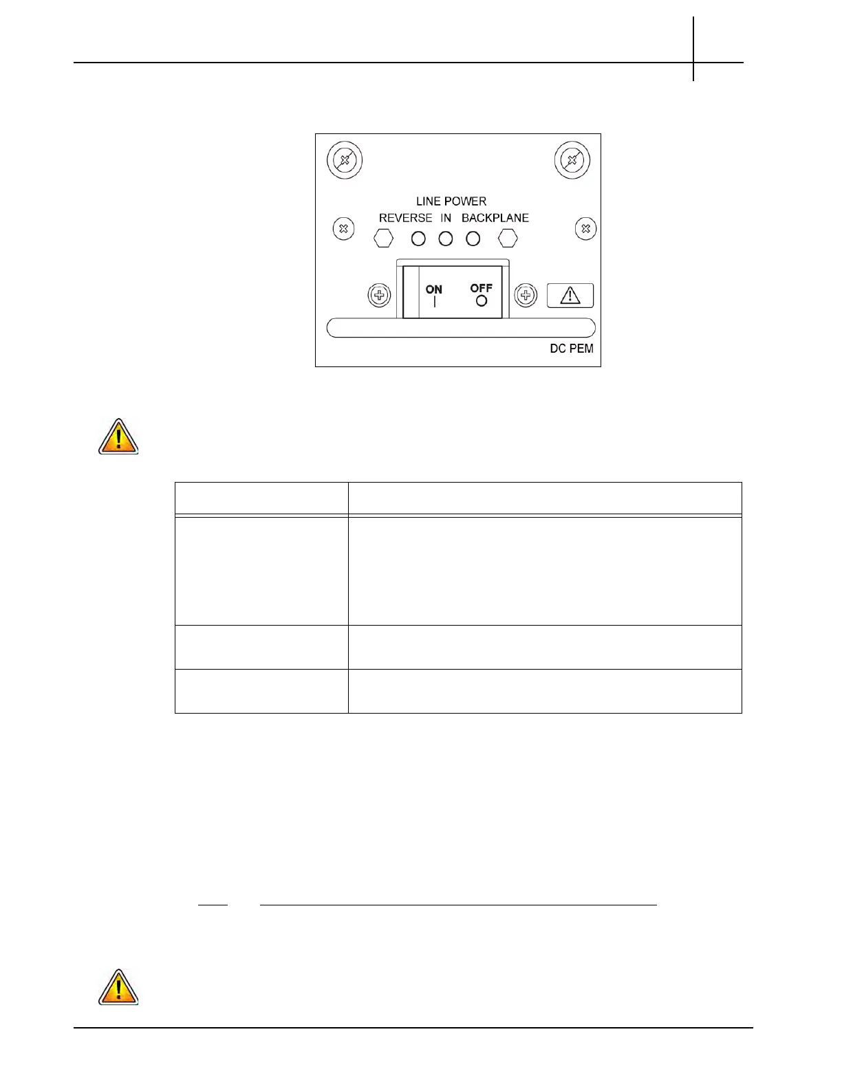
12. Check the PEM LEDs (see Figure 5.2) and take the appropriate actions as
listed in Table 5.1.
Figure 5.2 - PEM LEDs
Applying reverse power causes damage to the electrolytic capacitors of the filter. Therefore,
switch on the breakers only if no red light is visible.
13. Switch the breaker to the ON position.
14. Verify that the green BP LED (on the right) is lit.
Replacing an AC PEM
Perform the following steps to replace an AC PEM.
Step Action
1. Put on an ESD wrist strap.
Electrostatic discharge can damage circuits or shorten their life. Before touching the blade
or electronic components, ensure that you are working in an ESD-safe environment.
Table 5.1 - G10 DC PEM LEDs
PEM LEDs Status
Reverse LED (red)
ON
In LED (green) OFF
Do no
t switch on the breaker while the Reverse LED is on.
Reason—the power connected is reversed.
Action—turn off the feed power and attach the power
cables at the power connector with the correct orientation
(-48V, Return).
Reverse LED (red)
OFF
In LED (green) OFF
Do no
t switch on the breaker while the In LED st
ays off.
Reverse LED (red)
OFF
In LED (green) ON
T
he power is connected correctly. You may switch on the
br
eaker now.
Tektronix Communications | For Licensed Users | Unauthorized Duplication and Distribution Prohibited

 Loading...