G10 Hardware Maintenance Guide 7.13.2 90
5
Maintenance Guidelines
Rev. 002-140228
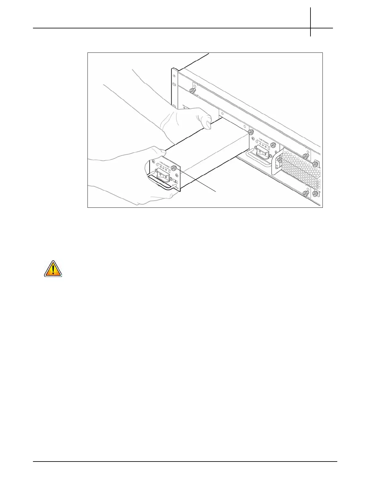
8. Insert the replacement PEM (see Figure 5.1).
Figure 5.1 - Inserting the Replacement DC PEM
9. Fasten the two PEM captive screws.
10. Reconnect the power cables to the PEM.
Tektronix equipment, cables, and wiring diagrams comply with industry standard DC
electrical color coding. Please ensure proper cabling if your equipment and cabling uses
nonstandard DC electrical color coding. Improper cabling can cause damage to equipment
or personal injury. Contact Tektronix to request specially labeled power cables (-48V = Red,
Return = Black) for the G10 chassis and the storage enclosures.
11. Turn on the feed power if it is not already turned on.
Tektronix Communications | For Licensed Users | Unauthorized Duplication and Distribution Prohibited

 Loading...