G10 Hardware Maintenance Guide 7.13.2 158
A
Rev. 002-140228
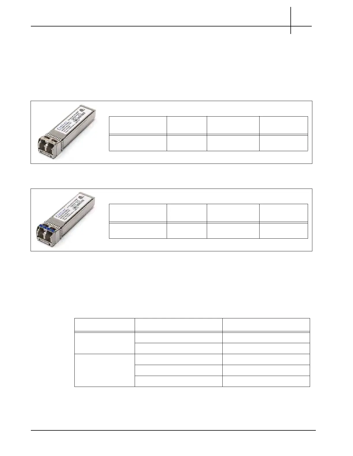
The four LC type optical connections use SFP+ transceiver modules for input of 10G Ethernet
links. The G10 10G Ethernet ports support the following fiber connectivity:
10Gbase-SR Fiber
10Gbase-LR Fiber
10Gbase-SR Fiber
10Gbase-LR Fiber
MINIMUM SIGNAL LEVELS
To accurately monitor links, a minimum signal strength is required at each G10 input port. The
signal strength requirement is broad enough to allow some amount of optical taps and
splitters. The Inputs must comply with Table A.1.
Distance Tek P/N Finisar P/N Handle color /
Shape
850 nm
multi-mode
119741700 FTLX8571D3BCL Light-grey/Flat
Distance Tek P/N Finisar P/N Handle color /
Shape
1310 nm
single-mode
119747500 FTLX1471D3BCL Blue/Flat
Table A.1 - Minimum Signal Levels
Interface Type Mode Minimum Signal Level
10 GB Ethernet 850 nm multi-mode -9 dBm (0 dBm maximum)
1310 nm single-mode -12 dBm (0 dBm maximum)
1 GB Ethernet 850 nm multi-mode (SC) -16 dBm (0 dBm maximum)
1300/1310 nm multi-mode (LX) -18 dBm (0 dBm maximum)
1310 nm single-mode (LX) -20 dBm (0 dBm maximum)
Tektronix Communications | For Licensed Users | Unauthorized Duplication and Distribution Prohibited

 Loading...