G10 Hardware Maintenance Guide 7.13.2 39
3
Blades and RTMs
Rev. 002-140228
IIC200 RTMs
The IIC200 supports the following RTM configuration options for deployment:
IIC200 and the SRM200 RTM
IIC200 and the TRM100 RTM (to support eHRPD Monitoring)
SRM200 RTM
The SRM200 RTM connects to the back of the G10 chassis in the upper slot location. It
performs the following functions (Figure 3.9):
Communicates the board’s health and configuration status to the IIC200
Provides two Gigabit Ethernet links for connectivity to controller enclosure
Sends and receives data to the disk array storage subsystem
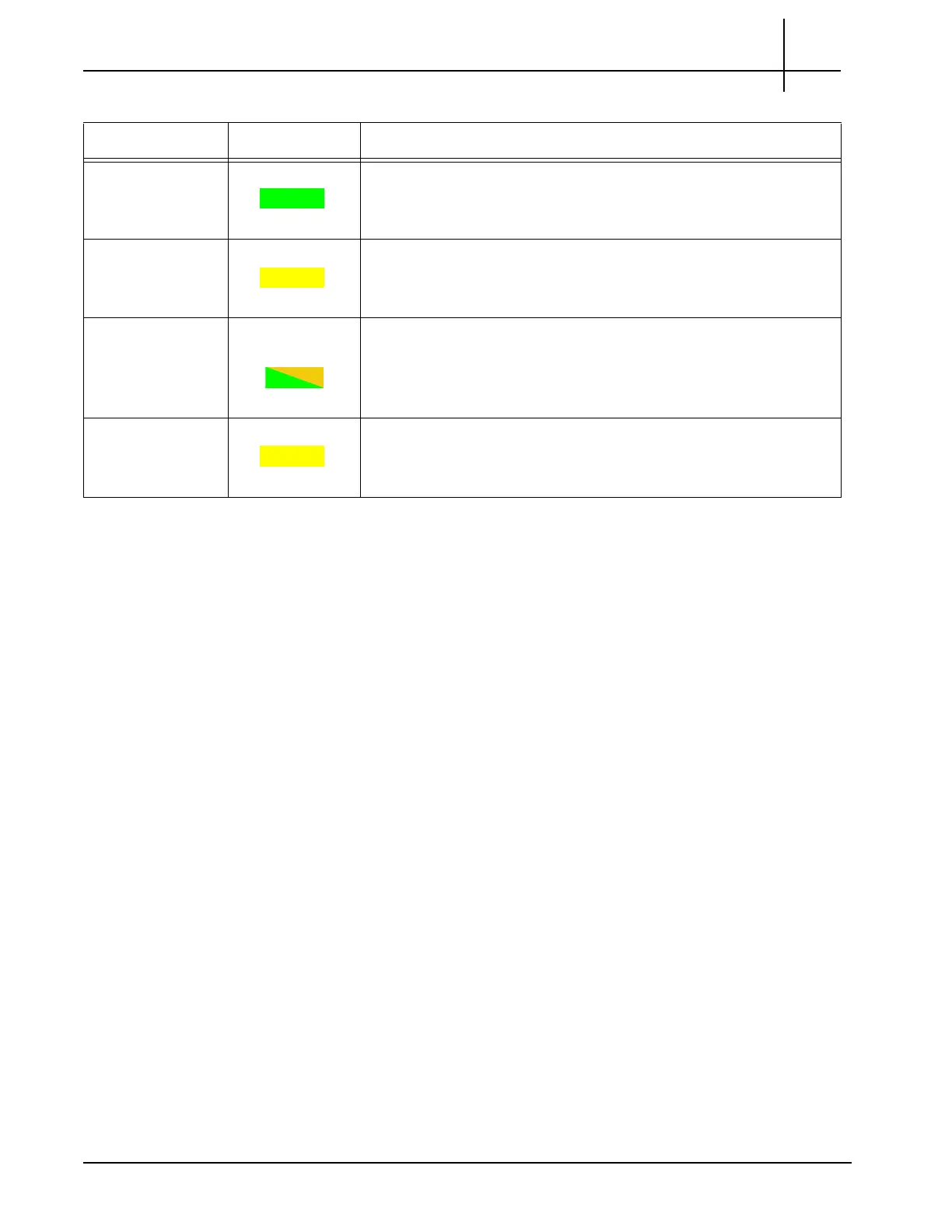
1 GbE Port 1-4
LNK
GREEN GbE Port Link Status Indicator
GREEN = The link is up.
1 GbE Port 1-4
ACT
YELLOW GbE Por
t Activity Status Indicator
YELLOW = Activity
1/10 GbE LNK GREEN or
AMBER
XGE port link status indicator
AMBER = The 10G Link is up.
GREEN = The 1G link is up.
1/10 GbE ACT YELLOW XGE port activity status indicator
YELLOW = Activity
Table 3.4 - LPC200 AMC LEDs (Continued)
LE
D LED Color Description
Tektronix Communications | For Licensed Users | Unauthorized Duplication and Distribution Prohibited

 Loading...