G10 Hardware Maintenance Guide 7.13.2 38
3
Blades and RTMs
Rev. 002-140228
Table 3.3 describes the LPC200 AMC connectors.
LPC200 AMC LEDs
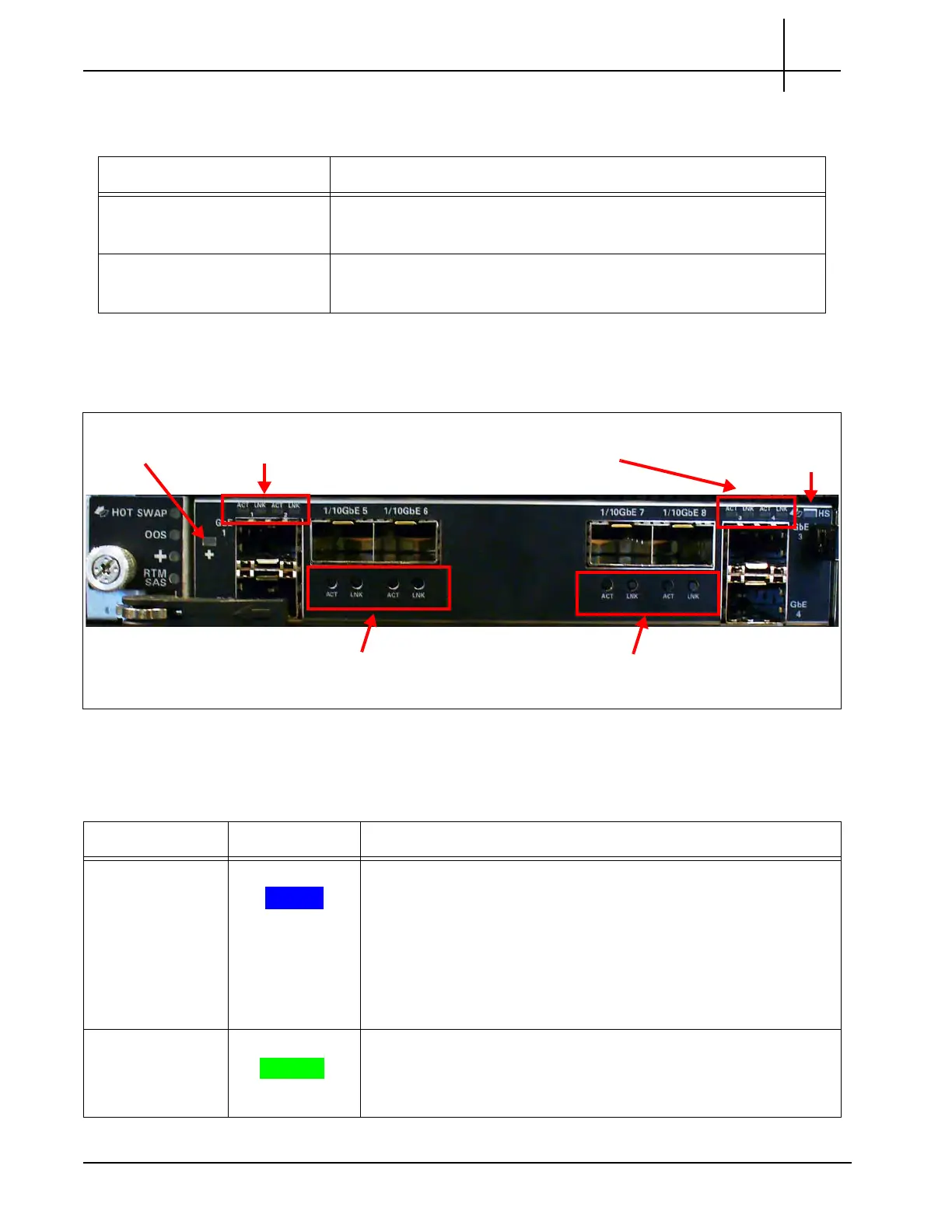
Figure 3.8 displays the LPC100 AMC LEDs.
Figure 3.8 - LPC200 AMC LEDs
Table 3.4 describes the LPC200 AMC LEDs.
Table 3.3 - LPC200 AMC Connectors
LED Description
1 GbE Ports 1–4
Support 1G Ethernet traffic
Support copper or fiber SFP/SFP+s
1/10 GbE Ports 5–8
Support 1G or 10G Ethernet traffic
Support fiber SFP/SFP+s
1/10 GbE Port 5 and 6
Activity and Link LED
Health
LED
Hot Swap
LED
1 GbE Port 1 and 2
Activity and Link LED
1 GbE Port 3 and 4
Activity and Link LED
1/10 GbE Port 7 and 8
Activity and Link LED
Table 3.4 - LPC200 AMC LEDs
LED LED Color Description
Hot Swap BLUE Hot Swap Indicator that indicates when it is safe to remove the
mod
u
le.
SOLID BLUE = The module is in standby mode and can be
safely extracted.
Off = The module is operational, and it is unsafe to extract it.
BLINKING BLUE = The module is in transition between
standby mode and operational mode.
+ GREEN Indicates the health of the device.
GREEN = No errors.
OFF = Out of service.
Tektronix Communications | For Licensed Users | Unauthorized Duplication and Distribution Prohibited

 Loading...