G10 Hardware Maintenance Guide 7.13.2 79
4
Storage Subsystem
Rev. 002-140228
DISK ENCLOSURE REAR PANEL
The components and LEDs on the disk enclosure rear panel vary depending on whether it is a
controller enclosure or an expansion enclosure.
Tektronix equipment, cables, and wiring diagrams comply with industry standard DC
electrical color coding. Please ensure proper cabling if your equipment and cabling use
nonstandard DC electrical color coding. Improper cabling can cause damage to equipment
or personal injury. Contact Tektronix to request specially labeled power cables (-48V = Red,
Return = Black) for the G10 chassis and the storage enclosures.
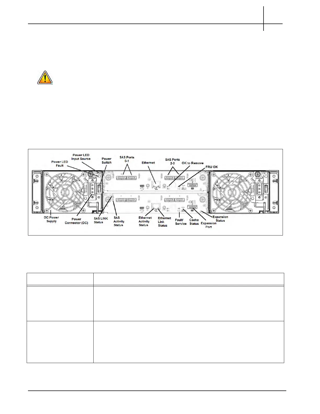
SA200R Controller Enclosure Rear Panel
The controller enclosure rear panel houses SAS and Ethernet port connectors, power
supplies, and power switches (see Figure 4.4).
Figure 4.4 - SA200R Controller Enclosure Re
ar Panel (DC Power Supplies Shown)
Table 4.2 displays the SA200R Controller En
closure Rear Panel LEDs.
Table 4.2 - SA200R Controller Enclosure Rear Panel LEDs
LED Description
Power Supply Input
Source
This LED displays the color GREEN and indica
te
s whether the input source
power is good. Valid options are:
ON—The power is on, and input voltage is normal.
OFF—The power is off, or input voltage is below the minimum threshold.
Power Supply Fault This LED displays the color YELLOW and indicates the DC Voltage/Fan Fault/
Service
Required. Valid options are:
ON—The DC output voltage is out of range, or a fan is operating below the
minimum required RPM.
OFF—The DC output voltage is normal.
Tektronix Communications | For Licensed Users | Unauthorized Duplication and Distribution Prohibited

 Loading...