G10 Hardware Maintenance Guide 7.13.2 84
4
Storage Subsystem
Rev. 002-140228
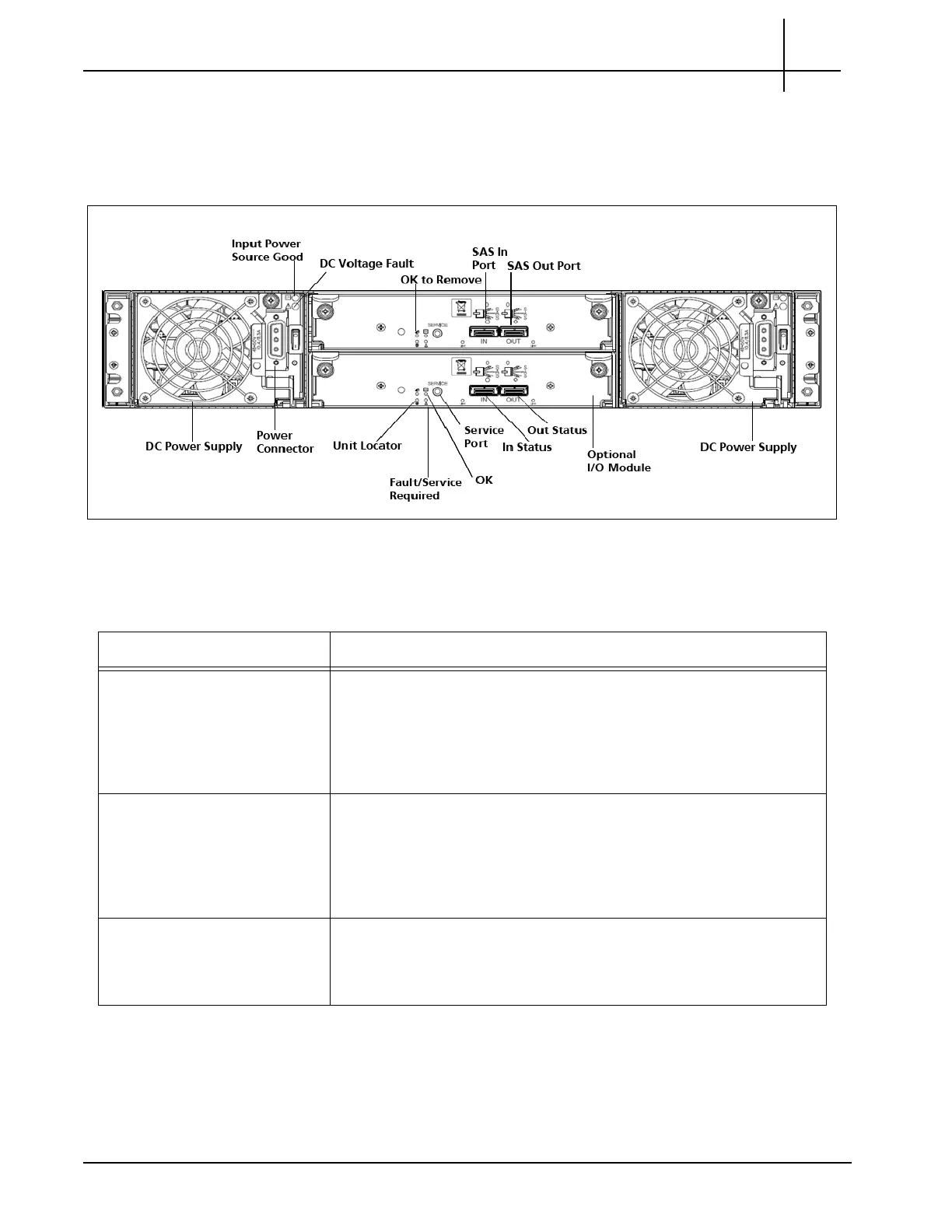
SA100J, SA200J, and SA210J Expansion Enclosure Rear Panel
The expansion enclosure rear panel houses SAS IN/OUT port connectors, the power supplies,
and power switches (Figure 4.6).
Figure 4.6 - Expansion Disk Enclosure Rear Panel (DC Power Supplies Shown)
Table 4.6 displays the expansion disk enclosure LEDs.
Table 4.6 - Expansion Disk Enclosure LEDs
LED Description
Power Supply Input Source This LED displays the color GREEN a
n
d indicates whether the input
source power is good. Valid options are:
ON—The power is on, and input voltage is normal.
OFF—The power is off, or input voltage is below the minimum
threshold.
Power Supply Fault This LED displays the color YELLOW and indicates the DC Voltage/
Fa
n Fault/Service Required. Valid options are:
ON—The DC output voltage is out of range, or a fan is operating
below the minimum required RPM.
OFF—The DC output voltage is normal.
Unit Locator This LED displays the color WHITE. Valid options are:
OFF—Normal operation.
BLINKING—Physically identifies the controller module.
Tektronix Communications | For Licensed Users | Unauthorized Duplication and Distribution Prohibited

 Loading...