G10 Hardware Maintenance Guide 7.13.2 145
6
System Operating Specifications
Rev. 002-140228
POWER AND GROUND REQUIREMENTS
The following sections list the power and ground requirements for the GeoProbe G10 and
storage enclosures.
Both units will require individual connec
tions to earth ground for safety. The GeoProbe G10
provides dual-post connection for this purpose. The disk enclosure power cable includes an
earth ground connection. All cables with the exception of the Power and Fiber Optics cables
shall be shielded. Make sure that a suitable -40.0 to -72 VDC power source is within reach of
the system. Two power entry modules (PEMs) can be installed in the system.
The system is supplied by a TNV-2 voltage. This voltage is considered hazardous. Make
sure that the external power supply meets the relevant safety standards. Ensure that TNV-2
is separated from dangerous voltages (mains) through double or reinforced insulation.
DC Power Requirements
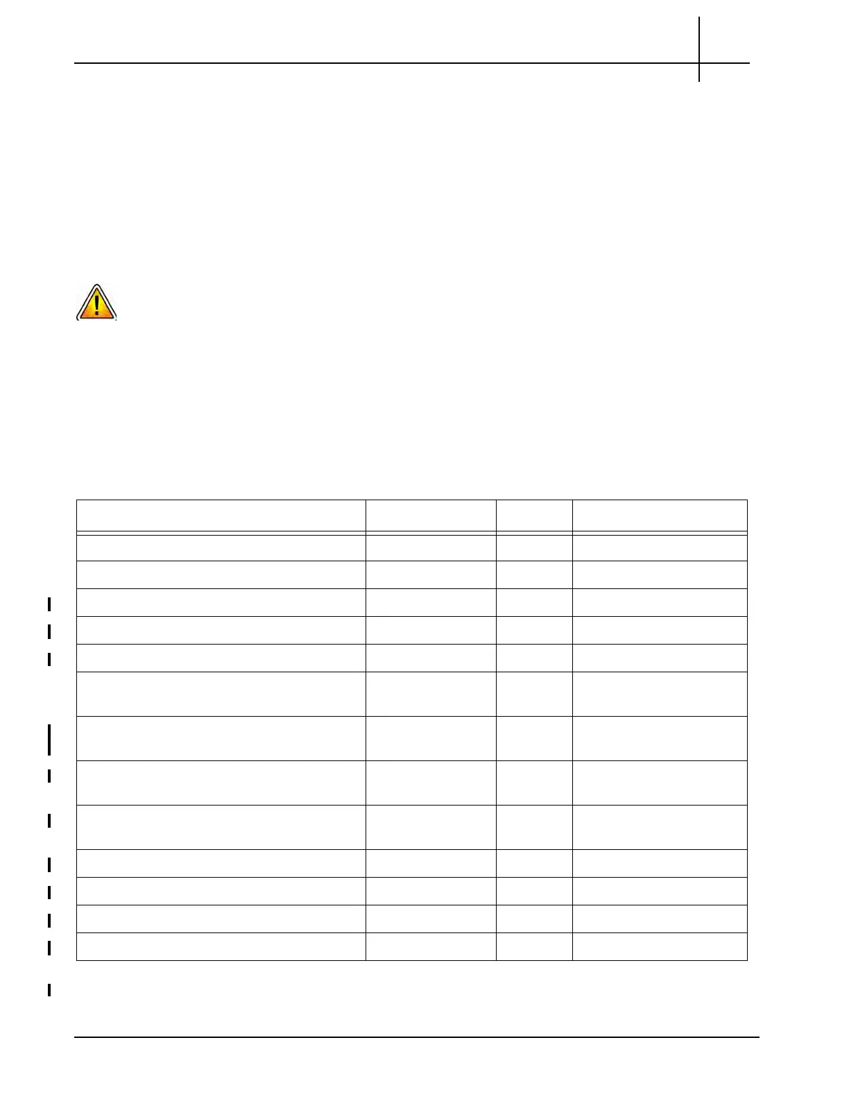
Table 6.1 lists the DC power requirements for the GeoProbe G10 and SAS storage
enclosures. All probe and disk enclosure power and
chassis ground cabling use 12AWG cable
or larger.
Table 6.1 - DC Power Requirements
Equipment VDC Fuse Watts
G10 (IIC100 and IAP100) -40 to -72VDC 15A max 430W typical, 600W max
G10 (IIC100 and IAP200) -40 to -72VDC 15A max 470W typical, 600W max
G10 (IIC100 and IAP320)
a
-40 to -72VDC 15A max 495W typical, 600W max
G10 (IIC200 and IAP200) -40 to -72VDC 15A max 495W typical, 600W max
G10 (IIC200 and IAP320) -40 to -72VDC 15A max 495W typical, 600W max
G10 Media Expansion Chassis
(2 IIC100s and 2 TRM100 RTMs)
-40 to -72VDC 15A max 460W typical, 600W max
G10 Media Expansion Chassis
(2 IIC200s and 2 SRM200 RTMs)
-40 to -72VDC 15A max 460W typical, 600W max
G10 Control Plane Expansion Chassis
(2 IAP200s and 2 PRM200 RTMs)
-40 to -72VDC 15A max 470W typical, 600W max
G10 Control Plane Expansion Chassis
(2 IAP320s and 2 PRM300 RTMs)
-40 to -72VDC 15A max 530W typical, 600W max
SA100R RAID Storage Enclosure -40 to -72VDC 15A max 280W typical, 500W max
SA100J JBOD Storage Enclosure -40 to -72VDC 15A max 280W typical, 500W max
SA200R RAID Storage Enclosure
b
-40 to -72VDC 15A max 420W typical, 500W max
SA200J/SA210J JBOD Storage Enclosure
b
-40 to -72VDC 15A max 255W typical, 500W max
a. The control plane probe does not support the IIC100/IAP320 configuration.
b. For Storage Enclosure and 24 900G drives (SA200J) or 12 4TB drives (SA210J).
Tektronix Communications | For Licensed Users | Unauthorized Duplication and Distribution Prohibited

 Loading...