G10 Hardware Maintenance Guide 7.13.2 139
5
Maintenance Guidelines
Rev. 002-140228
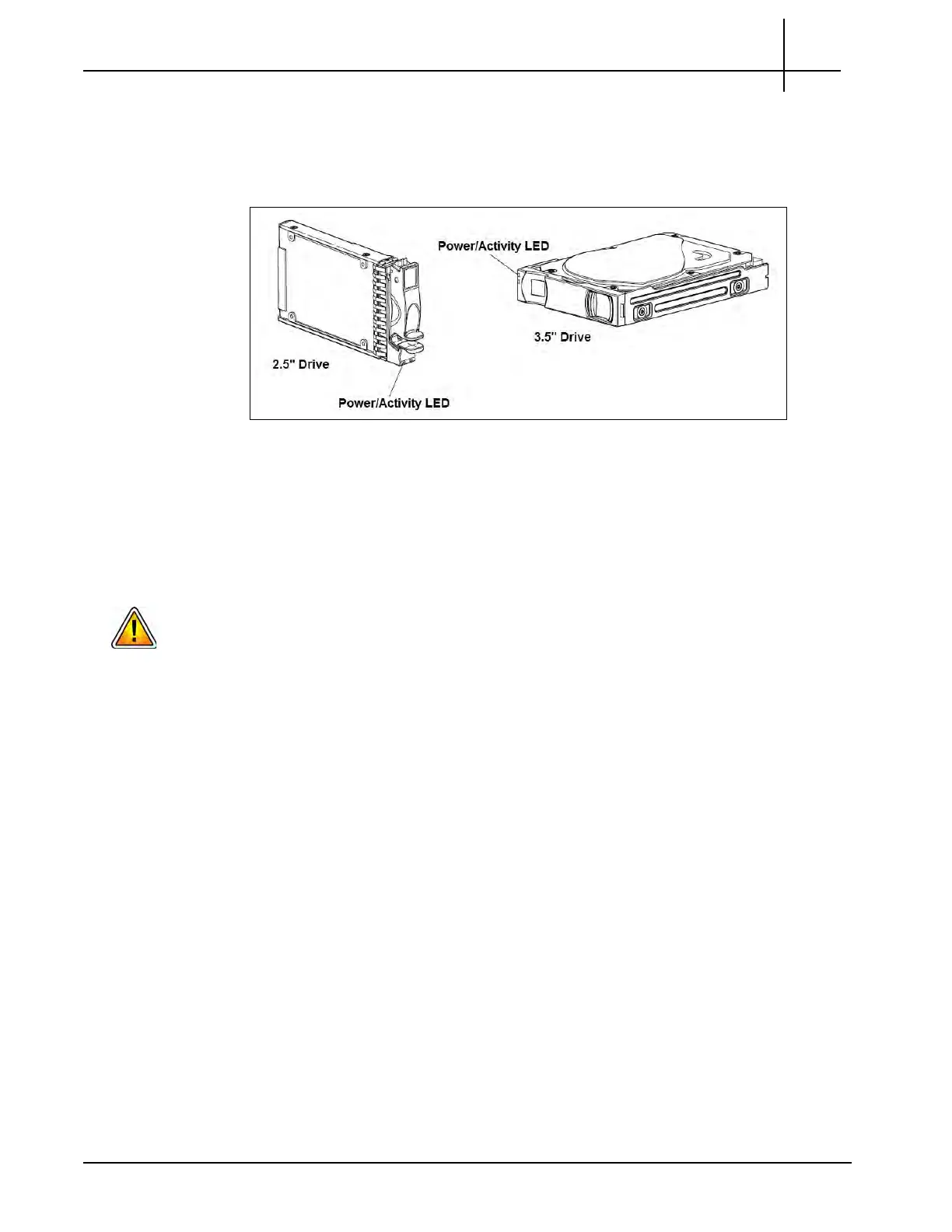
3. Rotate the latch inward until it clicks closed to firmly seat the drive module in the
enclosure’s midplane.
4. Check that the Power/Activity LED located
on the drive is
illuminated green (see
Figure 5.53).
Figure 5.53 - Drive Module LEDs
5. Contact Tektronix Communications Customer Supp
or
t for assistance in bringing
the disk drive into service.
Replacing the Disk Array Chassis
Prior to replacing the disk array chassis, you MUST power down the probe. See the Power
Down Procedure for details on powering down the probe.
Prior to replacing the disk array chassis, see the Iris Installation and Upgrade Guide to
perform the required G10 Probe Health Check. Contact Tektronix Communications
Customer Support for assistance.
Identify which disk array is being replaced (Controller 0, Controller 1, or an Expansion Disk
array {JBOD}).
If you are replacing both controllers, special commands must be performed before and after
hardware replacement. Contact Tektronix Communications Customer Support for
assistance.
Verify that all cables, terminating at the disk array, are properly labeled. Record the cable
connections, for use when reconnecting the cables.
Be sure to review Storage Array Maintenance Guidelines before proceeding to ensure
component compatibility.
Tektronix Communications | For Licensed Users | Unauthorized Duplication and Distribution Prohibited

 Loading...