G10 Hardware Maintenance Guide 7.13.2 24
2
Chassis Subsystem
Rev. 002-140228
Rear Panel LEDs
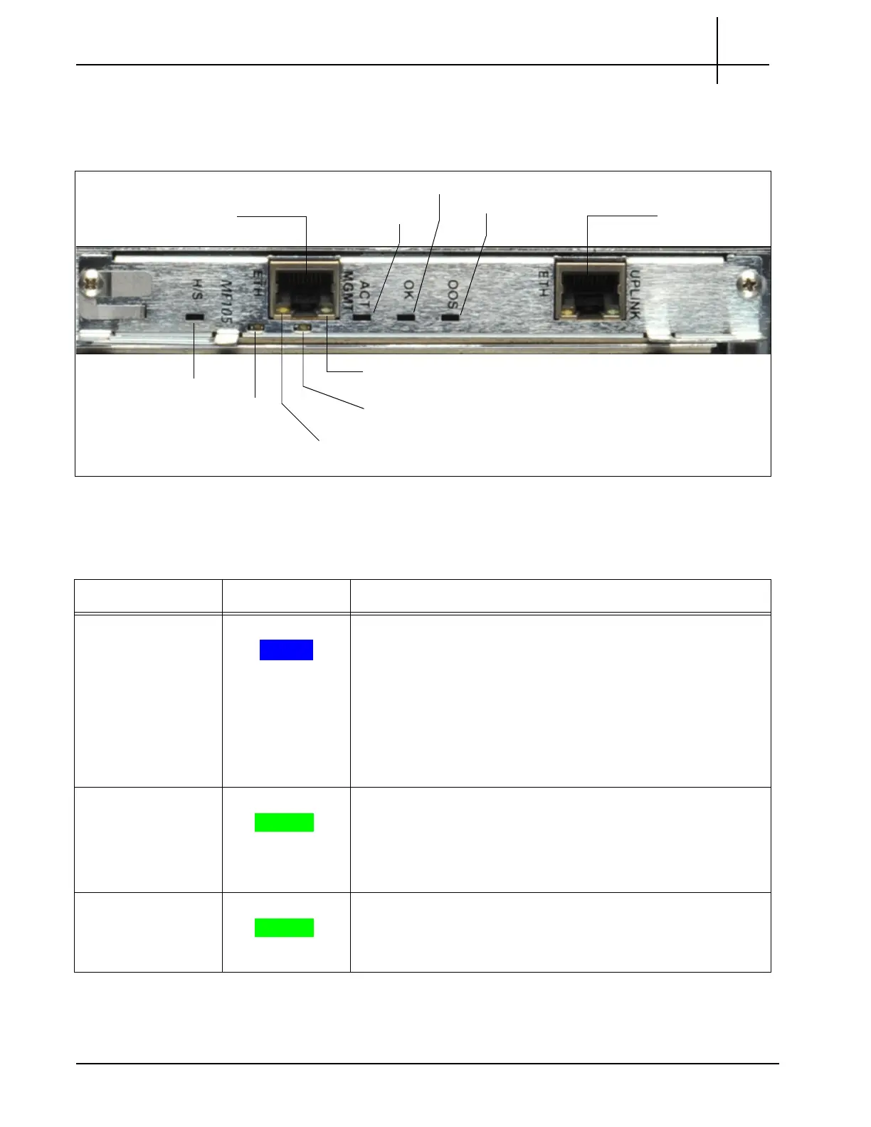
Figure 2.2 shows the SHmm LEDs on the rear of the G10.
Figure 2.2 - SHmm LEDs
Table 2.1 describes the SHmm LED indicators.
Base Channel 1
Ethernet Management Link
Base
Channel 2
Ethernet
Management Activity
Hot Swap Indicator
ACT MGMT
OK
OOS
Ethernet
Management
Connector
Ethernet
Uplink
Connector
Table 2.1 - LED Indicators of the Shmm
LED LED Color Description
H/S BLUE Hot Swap Indicator. It indicates when it
is safe to
remove the
module.
SOLID BLUE—The module is in standby mode and can be
safely extracted.
OFF—The module is operational, and it is unsafe to
extract it.
BLINKING—The module is in transition between standby
mode and operational mode.
Base Channel 1 GREEN Indicates the Ethernet connection to the chassis 1
G backplane.
GREEN—The link to base channel 1 is available.
BLINKING—Link and activity.
OFF—Otherwise.
Ethernet
Mana
gement Link
GREEN Indicates system manager Ethernet link availability.
GREEN—The link is available.
OFF—Otherwise.
Tektronix Communications | For Licensed Users | Unauthorized Duplication and Distribution Prohibited

 Loading...