G10 Hardware Maintenance Guide 7.13.2 27
2
Chassis Subsystem
Rev. 002-140228
Both A and B side power modules operate within the specifications listed in Power and
Ground Requirements. All probe power and chassis ground c
abling will use 12AWG cable or
larger.
Tektronix equipment, cables, and wiring diagrams comply with industry standard DC
electrical color coding. Please ensure proper cabling if your equipment and cabling use
nonstandard DC electrical color coding. Improper cabling can cause damage to equipment
or personal injury. Contact Tektronix to request specially labeled power cables (-48V = Red,
Return = Black) for the G10 chassis and the storage enclosures.
Front Panel LEDs
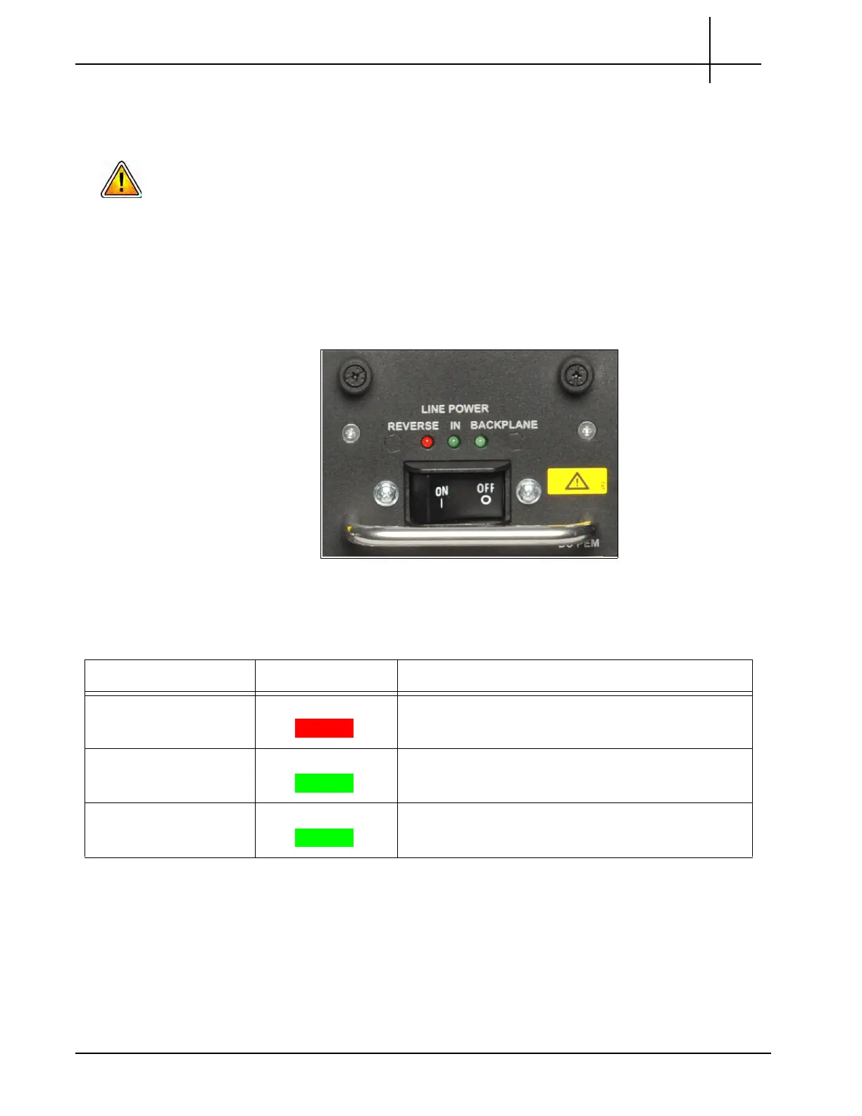
Figure 2.4 displays the DC Front Panel PEM LEDs and the ON and OFF switch.
Figure 2.4 - DC PEM Front Panel LEDs and ON/OFF Switch
Table 2.3 describes the DC PEM LED indicators.
Table 2.3 - DC PEM LED Indicators
LED LED Color Description
Line Power Reverse RED Indicates the connected power is reversed. Do not
swit
ch on the breaker while this LED is on.
Line Power In GREEN Indicates the power is connected properly.
Line Power Backplane GREEN Indicates the power module is sending power from the
ba
ckp
lane.
Tektronix Communications | For Licensed Users | Unauthorized Duplication and Distribution Prohibited

 Loading...