G10 Hardware Maintenance Guide 7.13.2 26
2
Chassis Subsystem
Rev. 002-140228
POWER ENTRY MODULES (PEMS)
The chassis includes two removable PEMs. The dual PEMs allow for two separate AC or DC
power feeds to the system. Both power feeds are fully distributed to every module and
subassembly within the chassis. Only one of the PEMs must be present for the chassis to be
fully operational.
The G10 supports both DC PEMs and AC PEMs. The PEMs are accessible from the front of
the shelf and connect to the PEM connectors on the
backplane. A removable plastic housing
covers the power feeds and returns to prevent accidental shorting. The PEM also features an
injector/ejector handle that provides the hot swap mechanism for signaling the state of the
PEM prior to removal. The PEM is an Field Replaceable Unit (FRU).
The PEMs are hot-swappable and will not cause a fault
when one is removed for
replacement.
They operate in load sharing where the total load is equal to or less than what one power feed
can provide.
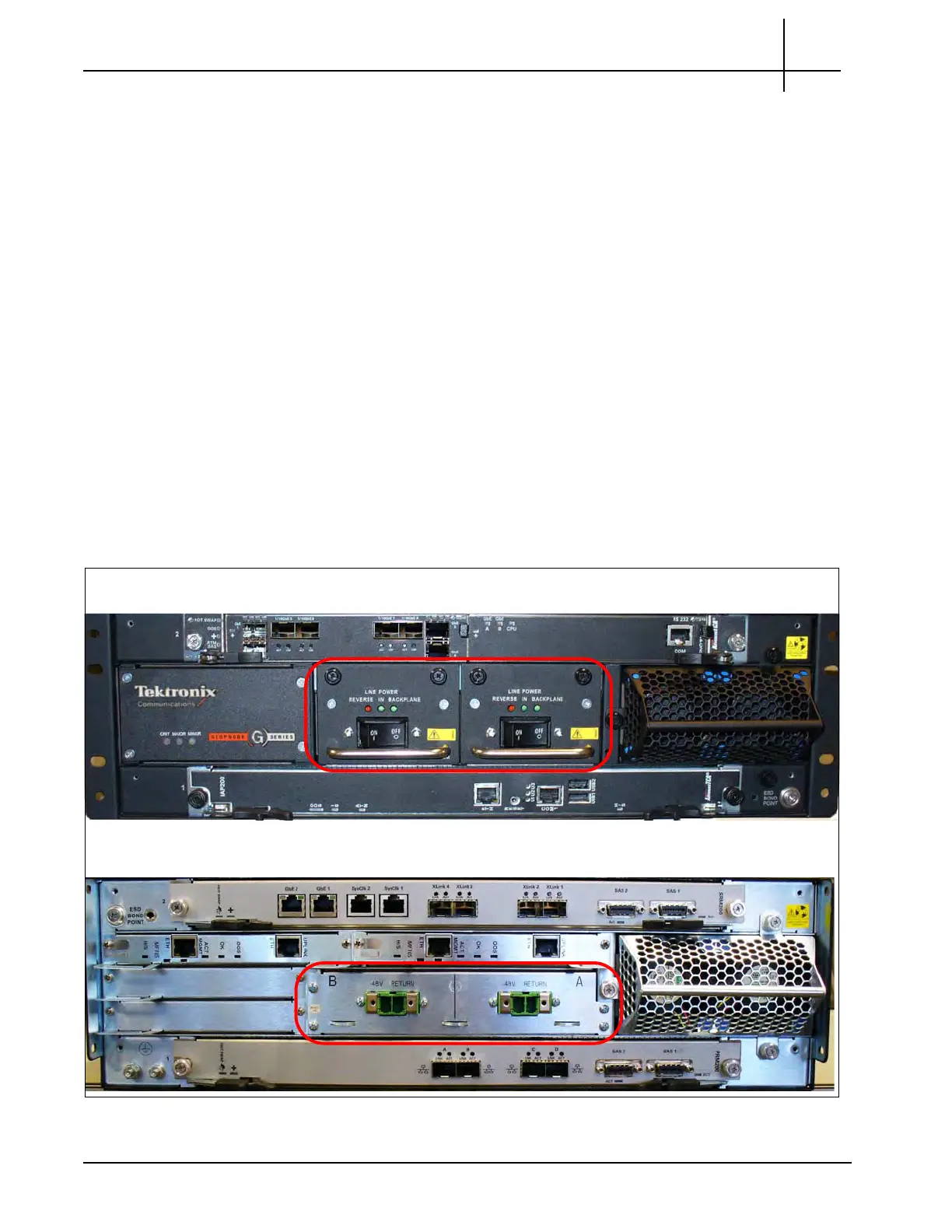
DC PEMs
Figure 2.3 shows the G10 DC PEMs front view and back view. Both A and B side power
modules operate within the specifications listed in Power and Ground Requirements. Refer to
Maintenance Guidelines for replacement details.
Figure 2.3 - DC PEMs
G10 Front View
G10 Rear View
Tektronix Communications | For Licensed Users | Unauthorized Duplication and Distribution Prohibited

 Loading...