G10 Hardware Maintenance Guide 7.13.2 138
5
Maintenance Guidelines
Rev. 002-140228
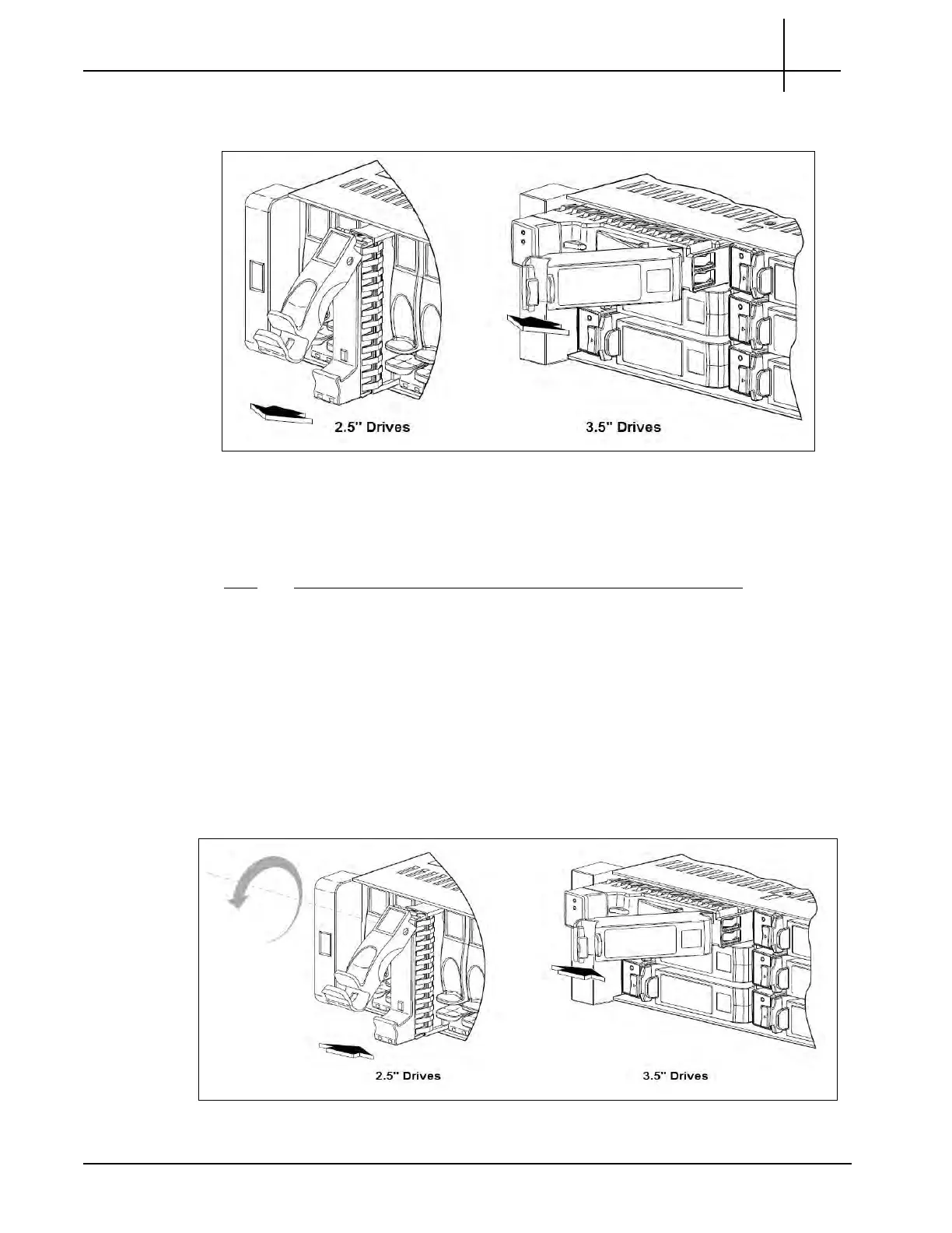
3. Pull the drive module straight out of the chassis (see Figure 5.51). Return the
failed disk and carrier to Tektronix Communications.
Figure 5.51 - Removing an AMS
Installing Drive Modules
Step Action
1. On new drive, prior to inserting, squeeze the latch release flanges together, and
then pull the latch, rotating it outward until it is fully open.
2. Perform one of the following steps, accordin
g to
your product’s drive type (see
Figure 5.52):
2.5” Drives—With the LEDs oriented to the bottom, slide the drive module
into the drive slot as far as it will go.
3.5” Drives — with the LEDs oriented to the left, slide the drive module into
the drive slot as far as it will go (see Figure 5.52).
Figure 5.52 - Installing a Drive Module
Tektronix Communications | For Licensed Users | Unauthorized Duplication and Distribution Prohibited

 Loading...