G10 Hardware Maintenance Guide 7.13.2 52
3
Blades and RTMs
Rev. 002-140228
TRM100 RTM LEDs
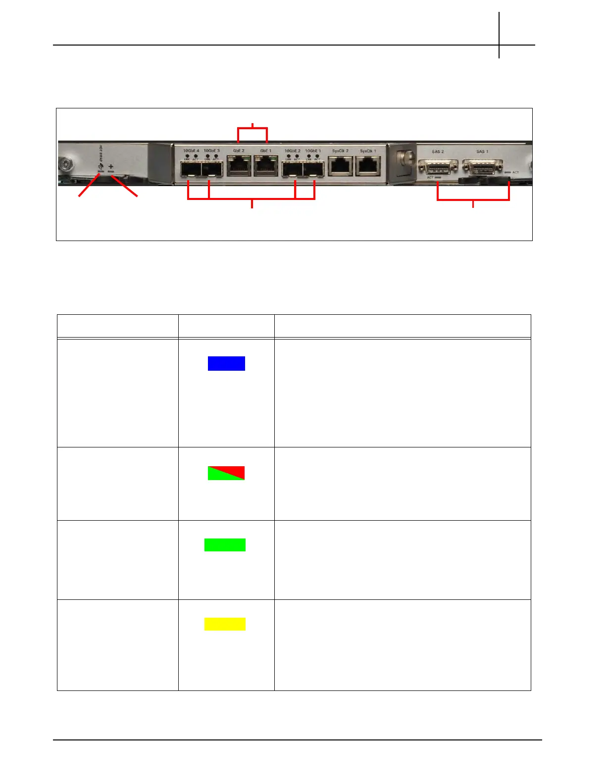
Figure 3.23 displays the TRM100 RTM LEDs.
Figure 3.23 - TRM100 RTM LEDs
Table 3.14 describes the TRM100 RTM LEDs.
GbE Activity LEDs
Hot Swap
LED
10GbE LNK and ACT
Status LEDs
MMC Health
Status LED
SAS LEDs (2)
Table 3.14 - TRM100 RTM LED Indicators
Connector/LED LED Color Description
Hot Swap BLUE
Indicates when it is safe to remove the module.
SOLID BLUE—module is in standby mode and can
be safely extracted.
OFF—module is operational and it is unsafe to
extract it.
BLINKING BLUE—module is in transition between
standby mode and operational mode.
+ GREEN or RED
MMC health LED.
GREEN—no errors.
RED—error occurred.
OFF—board is not powered on.
LNK (10GbE) GREEN
Four 10-Gb link LEDs; one for each of the SFP+
modules. These indicate the status of the port
connectivity.
GREEN—10-Gb link is up.
OFF—no link established.
ACT (10GbE) YELLOW
Four 10-Gb activity LEDs; one for each of the SFP+
modules. These indicate the status of the traffic running
over the connection.
BLINKING YELLOW—10-Gb Ethernet activity
occurring.
OFF—no 10-Gb Ethernet activity.
Tektronix Communications | For Licensed Users | Unauthorized Duplication and Distribution Prohibited

 Loading...