G10 Hardware Maintenance Guide 7.13.2 59
3
Blades and RTMs
Rev. 002-140228
IAP200 Connectors
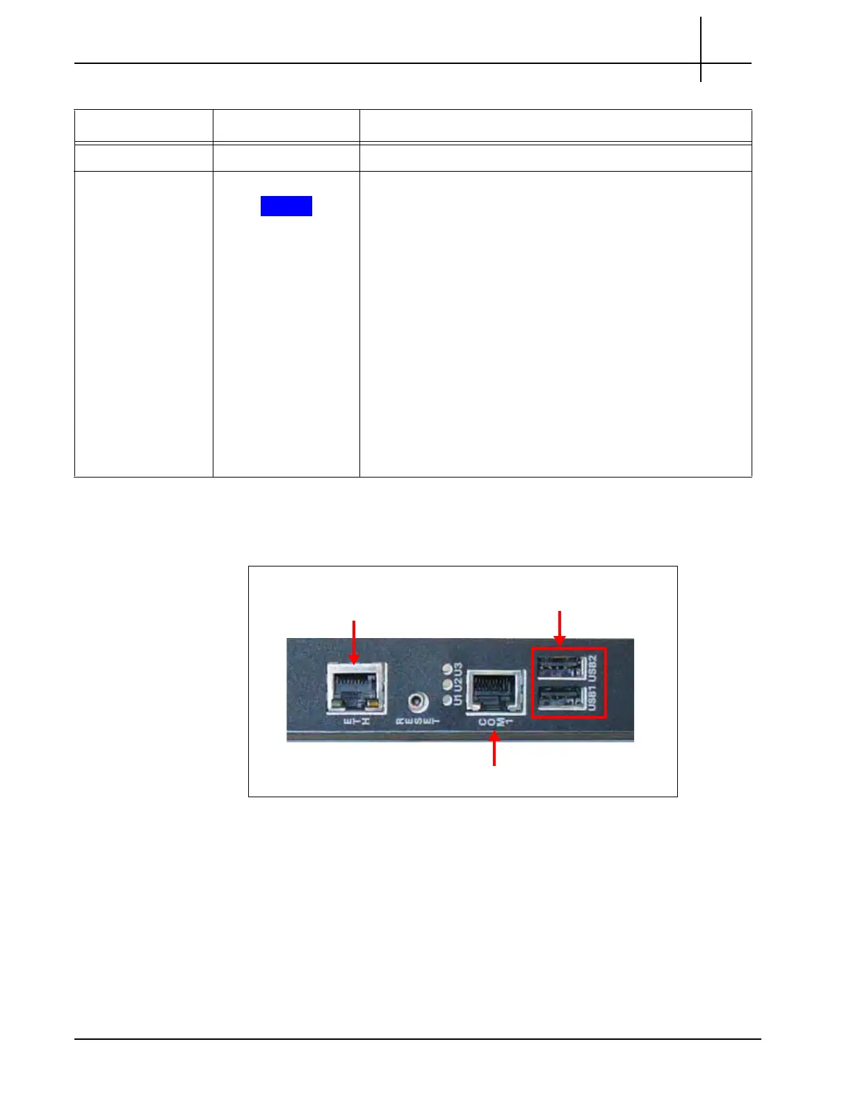
Figure 3.26 displays the IAP200 connectors.
Figure 3.28 - IAP200 Connectors
U1-U3 Not used.
H/S BLUE Indicates blade state machine st
atus an
d hot swap status.
During blade installation:
SOLID BLUE—The on-board IPMC powers up.
BLINKING BLUE—The blade communicates with shelf
manager.
OFF—The blade is active.
During blade removal:
SOLID BLUE—The blade is in standby mode and can be
safely extracted.
OFF—The blade is operational, and it is unsafe to extract
it.
BLINKING BLUE—The module is in a transition between
standby mode and operational mode.
Table 3.18 - IAP200 LED Indicators (Continued)
LED LED Color Description
ETH
USB Ports
Serial Console Port
Tektronix Communications | For Licensed Users | Unauthorized Duplication and Distribution Prohibited

 Loading...