HYDROSTATIC POWER TRAIN
4203780 First Edition 5-75
5
7. Remove the input bevel pinion assembly (8) and
differential assembly (6).
8. Place the shim pack in the bearing bore of the left
differential housing (9).
9. Install the input bevel pinion assembly (8) and
differential assembly (6). Apply Loctite 242 to input
bevel pinion housing screws (7) before assembly.
Install screws and tighten to 37 lb-ft (51 N·m).
10. Determine the shim thickness needed for the right
differential housing. (See “Determine Shim
Thickness” on page 5-76.)
Figure 5-83
11. Install the differential lock collar (14) and shim pack
(15) (as previously determined) in the right
differential housing (10).
12. Apply Loctite Primer to the mating surfaces of the
right (10) and left (17) differential housings.
13. Apply Loctite Gasket Eliminator 518 in a continuous
bead around the mating surfaces of the right (10) and
left (17) differential housings, making sure to go
around each hole.
14. Install two dowel sleeves (13) in the locations shown,
and assemble the right (10) and left (17) differential
housings.
15. Apply Loctite 242 to eight screws (11) before
assembly. Install screws and tighten to 37 lb-ft
(51 N·m).
16. Install plugs (16), drain plug (19) and seal (18)
(if removed).
17. Install breather (12) (If removed).
18. Install both drive axle reducer assemblies. (See
“Drive Axle Reducer Assembly” on page 5-69.)
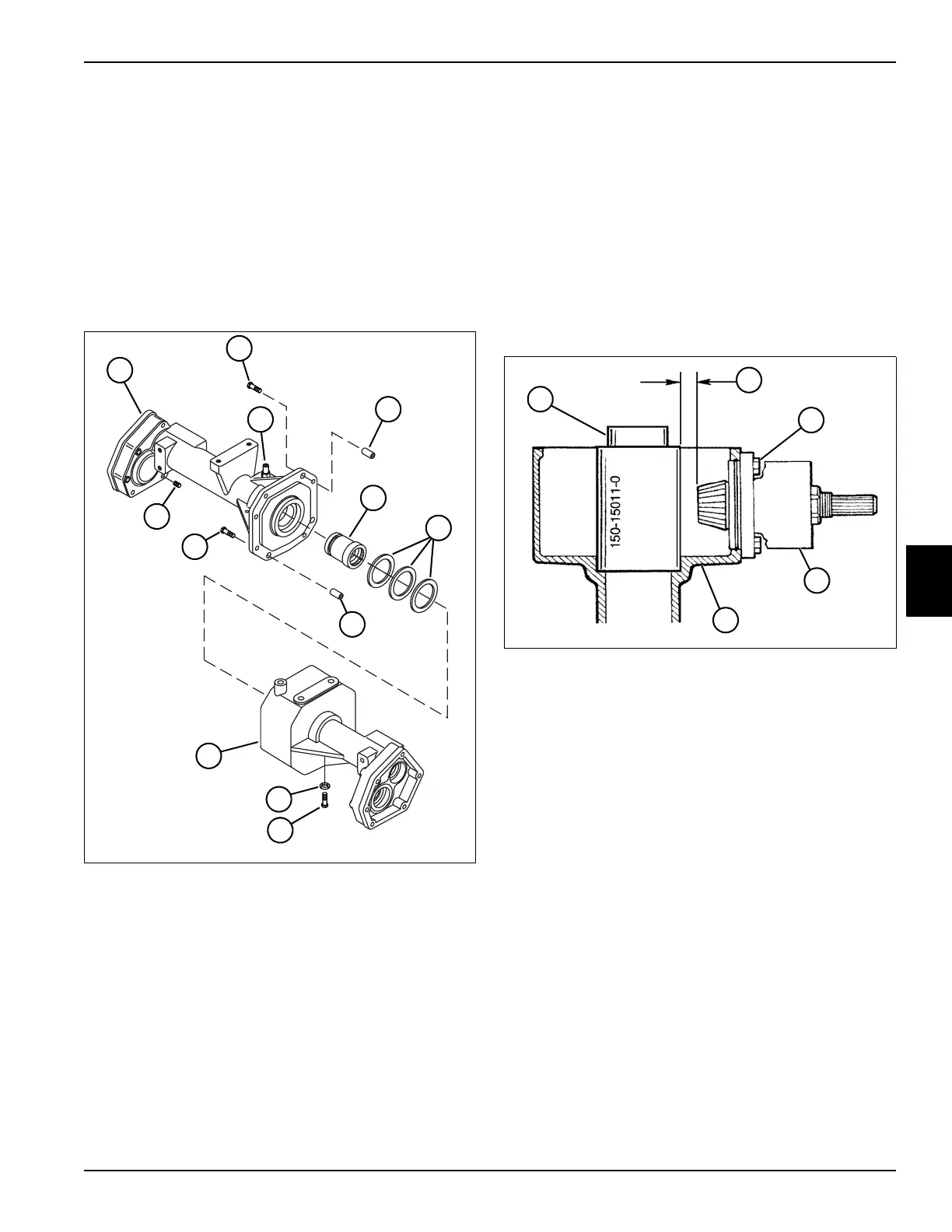
Input Bevel Pinion and Ring Gear Clearance
Adjustment
See Figure 5-84.
Figure 5-84
1. Install the input bevel pinion assembly (4) in the
differential housing (5). Do not install shim pack at
this time.
2. Install and tighten screws (3) to 37 lb-ft (51 N·m).
3. Install special tool (1) in the bearing bore of the
differential housing (5).
4. Measure the distance (2) between the face of the
pinion gear and the surface of the special tool (1).
5. Subtract the measurement obtained in step 4 from
0.689 in. (17.5 mm).
6. Remove the input bevel pinion assembly (4) from the
differential housing (5).
7. Build a shim pack to equal the final dimension
obtained in step 5.
8. Install the input bevel pinion assembly (4) and shim
pack on the differential housing (5).
9. Apply Loctite 242 to screws (3) before assembly.
Install screws and tighten to 37 lb-ft (51 N·m).
10. Remove special tool (1).
11. Proceed to “Assembly” on page 5-74.
TN1958
17
19
11
16
13
14
15
13
11
18
12
10
TN1916
4
5
3
1
2

 Loading...


