HYDROSTATIC POWER TRAIN
4203780 First Edition 5-79
5
Disassembly, Inspection, and Assembly
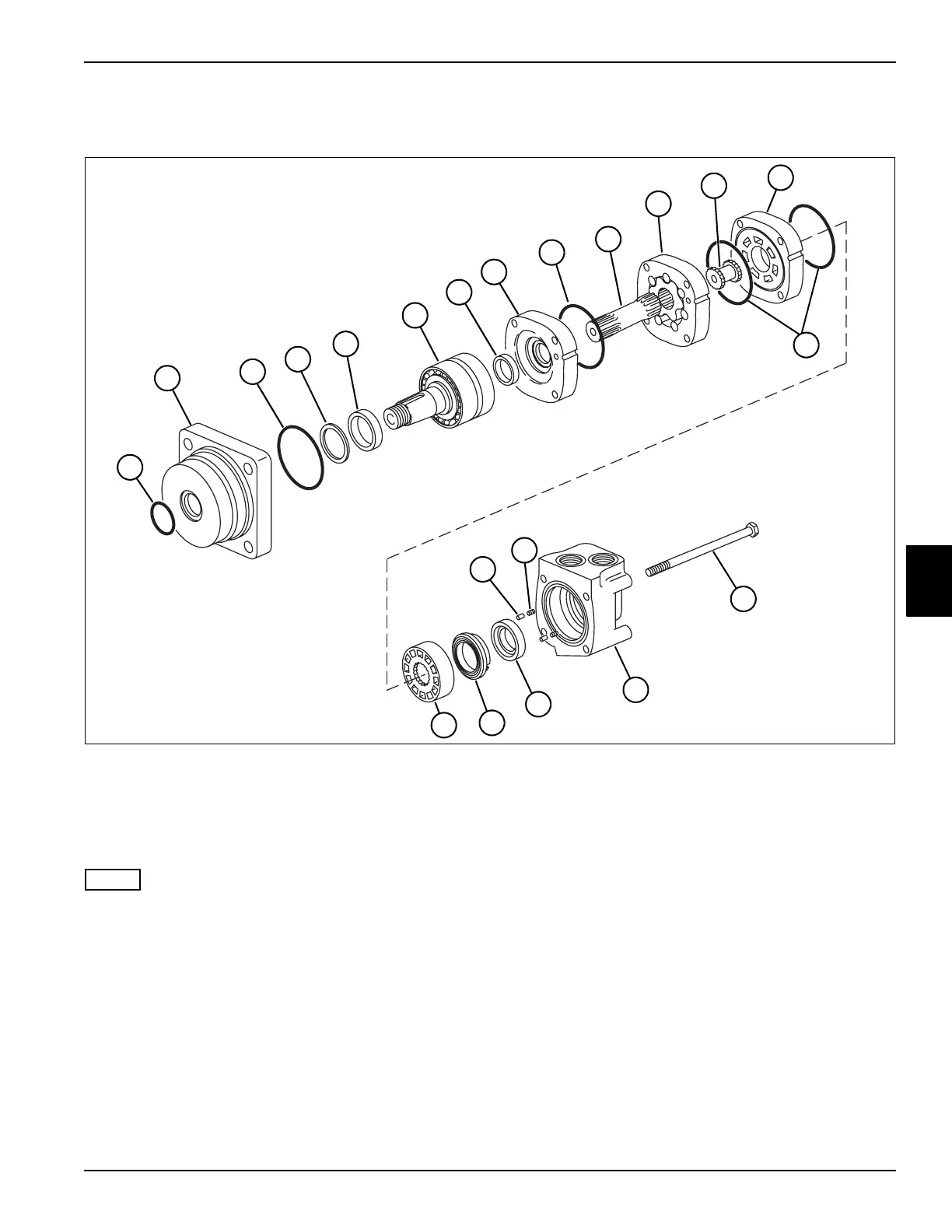
See Figures 5-92 and 5-93.
Figure 5-92
NOTE
When removing the port manifold cover (18) do not lose
the two pins (16) and springs (17) between the balance
ring (14) and the port manifold cover (18).
1. Disassemble rear wheel motor as shown.
2. Place parts in assembly order on a clean work area
as they are removed.
1 Seal, Exclusion 6 Shaft and Bearing Kit 11 Valve Drive 16 Pin (2)
2 Bearing Housing 7 Seal 12 Valve Plate 17 Spring (2)
3 O-Ring (4) 8 Wear Plate 13 Valve 18 Port Manifold Cover
4 Back-Up Ring 9 Drive 14 Balance Ring 19 Screw (4)
5 Shaft Seal 10 Geroler 15 Outer Face Seal
TN1779
1
2
3
4
5
6
8
3
9
10
12
7
15
13
14
18
19
3
11
16
17

 Loading...


