5-54 4203781 First Edition
HYDROSTATIC POWER TRAIN
5
8. Support the control valve (14).
9. Remove mounting screws (4), washers (5), lock
washers (6), and nuts (7).
10. Remove the control valve (14).
Installation Notes
• Install the control valve by reversing the order of
removal.
• Lubricate all O-rings prior to assembly.
• Make sure new O-rings are in place before installing
hoses on fittings.
• Replace hydraulic oil filter and charge pressure filter.
• Refill hydraulic tank. (Refer to “Safety, Operation, and
Maintenance Manual” for oil specifications.)
• Start engine. Check hydraulic system for leaks.
Repair as necessary.
• Check hydraulic oil level and add if necessary.
Disassembly, Inspection, and Assembly
See Figures 5-51 and 5-52.
NOTE
Repair of the control valve is limited to replacing
cartridges or replacing O-rings on each cartridge.
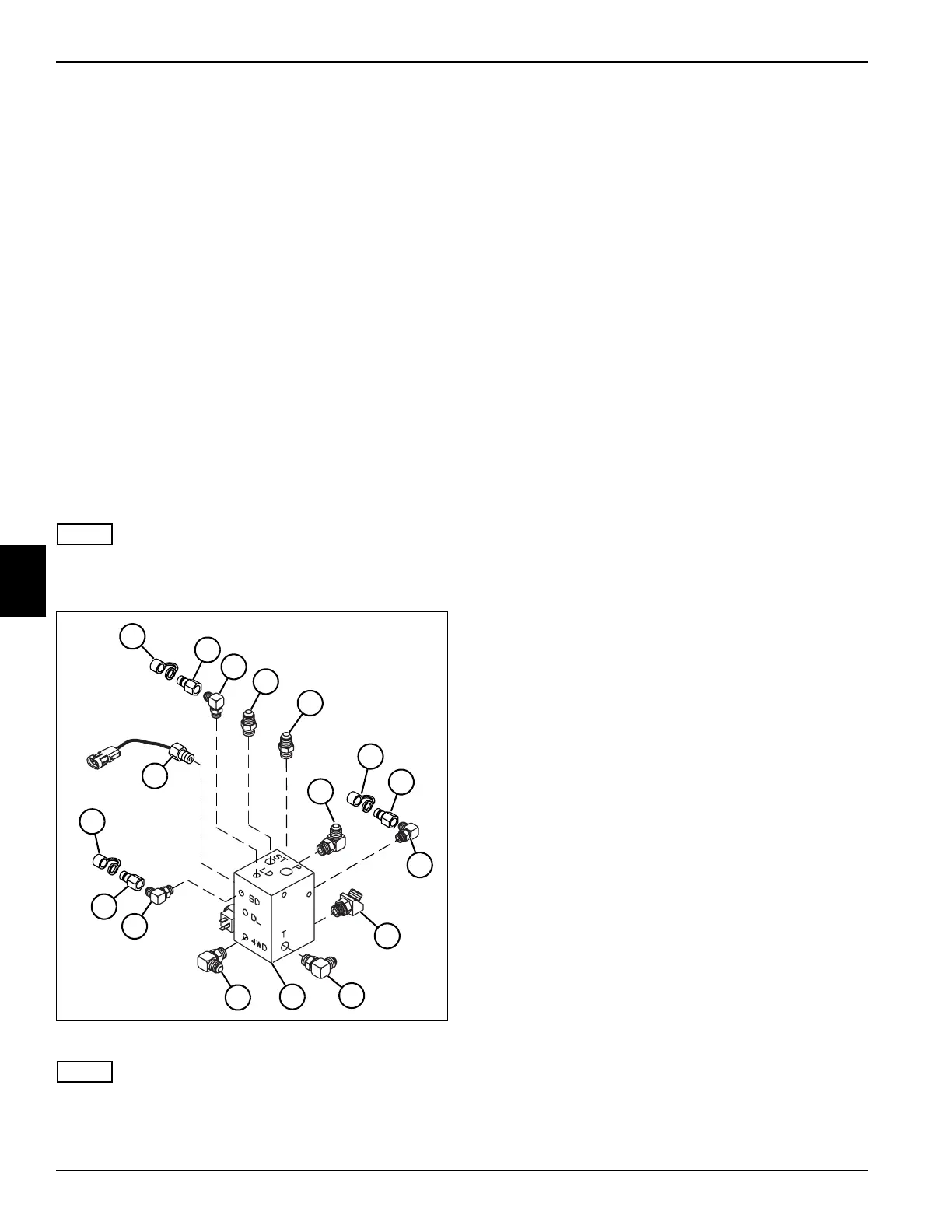
Figure 5-51
NOTE
Record the location and orientation of all fittings before
removing to ensure correct installation.
1. Remove dust cover (1), diagnostic port adapter (2),
and 90° adapter (3) from port “LD.”
2. Remove straight adapter (4) from port “ST.”
3. Remove straight adapter (5) from port “P.”
4. Remove 90° adapter (6) from port “L.”
5. Remove dust cover (7), diagnostic port adapter (8),
and 90° adapter (9) from port “CD.”
6. Remove 45° adapter (10) from port “F.”
7. Remove 90° adapter (11) from port “T.”
8. Remove 90° adapter (13) from port “4WD.”
9. Remove dust cover (16), diagnostic port adapter
(15), and 90° adapter (14) from port “SD.”
10. Remove charge pressure switch (17) from control
valve (12).
TN2335
1
16
5
17
2
6
7
14
11
10
9
13
3
4
15
8
12

 Loading...

