HYDROSTATIC POWER TRAIN
673831-Rev A 5-41
5
Disassembly, Inspection, and Assembly
See Figures 5-33 through 5-40.
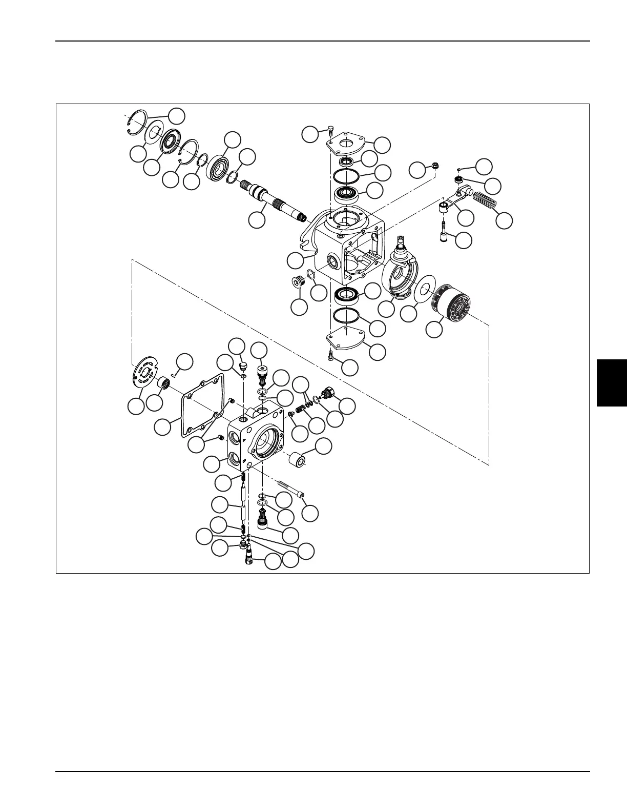
Figure 5-33
1 Internal Retaining Ring (2) 14 O-Ring (2)
27 Screw (4) 40 O-Ring
2 Seal Support Washer 15 Trunnion Cover 28 Loop Flushing Plug (2) 41 4060 psi Relief Valve (2)
3 Shaft Seal
16 Housing 29 O-Ring (2)
42 O-Ring (2)
4 External Retaining Ring (2) 17 Valve Plate 30 Spring (2) 43 O-Ring (2)
5 Ball Bearing 18 Slotted Pin 31 Loop Flushing Spool 44 Coupling, 9-Tooth
6 Input Shaft 19 Charge Relief Plug 32 Neutral Return Arm Assembly 45 Dowel Pin (2)
7
Swashplate
20 O-Ring
33 Cam Bearing 46 Plug Assembly
8 Thrust Plate 21 Charge Relief Shim Kit 34 Retaining Ring 47 O-Ring
9 35 cc Cylinder Block Kit 22 Charge Relief Spring 35 Neutral Return Spring
10 Trunnion Cover Assembly 23 Poppet 36 Neutral Return Pivot
11 Trunnion Shaft Seal
24 End Cap with Loop Flushing 37 Nut Seal
12 Trunnion Bearing Kit (2) 25 End Cap Gasket
38 Bypass Valve Assembly
Overhaul Seal and Gasket Kit
13 Screw (8) 26 Needle Bearing 39 Backup Ring
7
8
12
12
3
2
1
1
9
17
18
19
20
21
22
23
24
25
26
27
28
29
30
28
29
30
31
32
33
34
35
36
37
38
39
40
41
42
43
41
42
43
10
11
13
14
13
14
15
16
45
46
47
4
4
5
44
6

 Loading...

