HYDROSTATIC POWER TRAIN
673831-Rev A 5-43
5
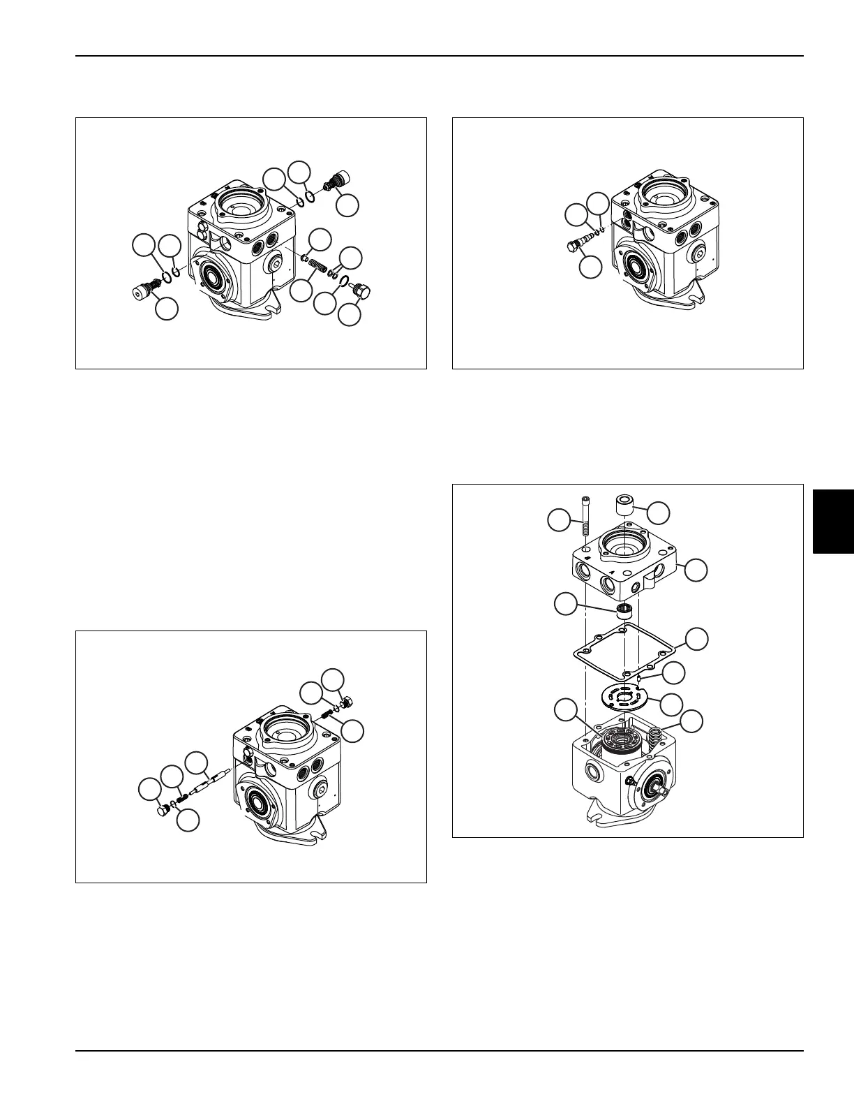
Relief Valves
Figure 5-36
1. Remove the charge pressure relief valve plug (19).
Remove and discard O-ring (20).
2. Remove shims (21) from charge relief plug (19) by
tapping the plug on the workbench.
3. Use a magnet to remove spring (22) and poppet (23).
4. Mark the locations of each high pressure relief valve
(41).
5. Remove the high pressure relief valves (41) from the
end cap. Remove and discard the O-rings (42 and
43)
Loop Flushing Valve
Figure 5-37
1. Remove the loop flushing valve plugs (28). Remove
and discard O-rings (29).
2. Use a magnet to remove springs (30) and loop
flushing valve (31).
Bypass Valve
Figure 5-38
1. Remove the bypass valve (38).
2. Remove back up ring (39) and O-ring (40).
End Cap
Figure 5-39
1. Remove coupling (44). Use a small hook if
necessary.
2. Remove four screws (27). Use caution when
loosening screws. Neutral return spring (35) is
putting pressure on the end cap.
3. Lift end cap (24) off pump housing. Remove gasket
(25).
4. Inspect bearing (26) in end cap (24). If wear is
visible, remove bearing.
31
28
29
30
28
29
30
9
17
18
24
25
26
27
35
44

 Loading...

