HYDRAULICS
673831-Rev A 6-51
6
Disassembly, Inspection, and Assembly
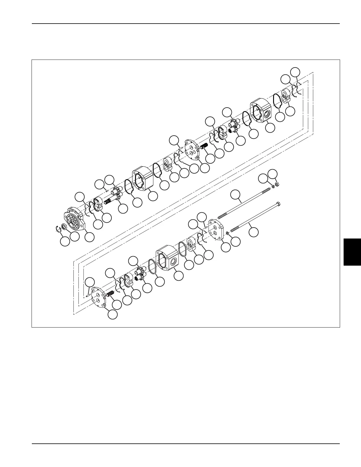
See Figures 6-54 and 6-55.
Figure 6-54
Disassembly Notes
• Do not disassemble pump for repair unless test
procedures indicate internal leakage.
• Never pry components apart. Use a soft face
hammer, and gently tap housing and shaft to
separate pump bodies.
• Scribe or mark the pump bodies and end covers
before disassembly to aid in assembly.
Recommended method of marking body sections is
to use a fine point metal punch, making one
indentation for section #1, two indentations for
section #2, etc.
1 Section 1, 0.403 in
3
Body 7 0.403 in
3
Drive Gear (2) 13 Section Seal (2) 19 Flange (Section 2-3)
2 Section 2, 0.403 in
3
Body 8 0.403 in
3
Input Shaft 14 Section Seal (4) 20 38 mm Drive Hub
3 Section 3, 0.403 in
3
Body 9 0.403 in
3
Driven Gear (3) 15 Shaft Seal 21 10 mm Dowel Pin (4)
4 Front Flange 10 Screw (4) 16 Retaining Ring 22 22 mm Dowel Pin (4)
5 Rear Flange 11 Washer (4) 17 Anti-Extrusion (6)
6 Thrust Plate (6) 12 Thrust Plate Seal (6) 18 Flange (Section 1-2)
1
2
3
4
5
6
6
6
6
6
6
7
7
8
9
9
9
10
11
12
13
13
14
14
14
14
14
14
15
16
15
16
16
16
17
18
19
19
19
19
19
19
20
21
22
22
23
24
23
24

 Loading...

