HYDRAULICS
673831-Rev A 6-57
6
Disassembly, Inspection, and Assembly
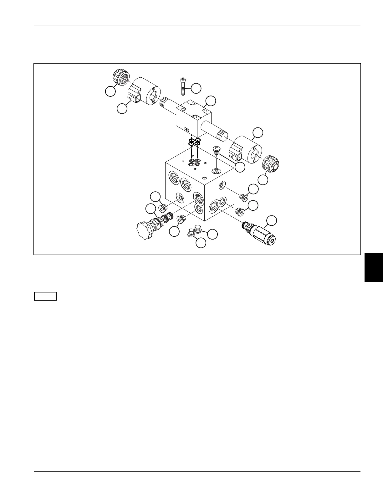
See Figure 6-61.
Figure 6-61
• Repair of the lift valve is limited to replacing valves
and cartridges or replacing O-rings.
• Record the location of the all cartridges before
removing to ensure correct installation.
• The solenoid coils (3 and 9) may appear the same,
but are different. The solenoid coils must be
assembled in the correct location.
1. Remove coil nuts (6) and solenoid coils (3 and 9).
2. Remove four solenoid valve screws (8) and solenoid
valve (2). Discard four O-rings between solenoid
valve and valve body.
3. Remove flow control valve (1). Remove and discard
O-rings and back-up rings.
4. Remove relief valve (7). Remove and discard O-rings
and back-up rings.
5. Remove plugs (4 and 5) and gauge port plug (9).
1 Flow Control Valve 4 -4 ORB Plug (3) 7 Relief Valve 10 Gauge Port Plug
2 D03 Solenoid Valve 5 -6 ORB Plug (3) 8 Solenoid Screw (4)
3 Mow Solenoid Coil 6 Coil Nut (2) 9 Backlap Solenoid Coil

 Loading...

