STEERING
673831-Rev A 7-17
7
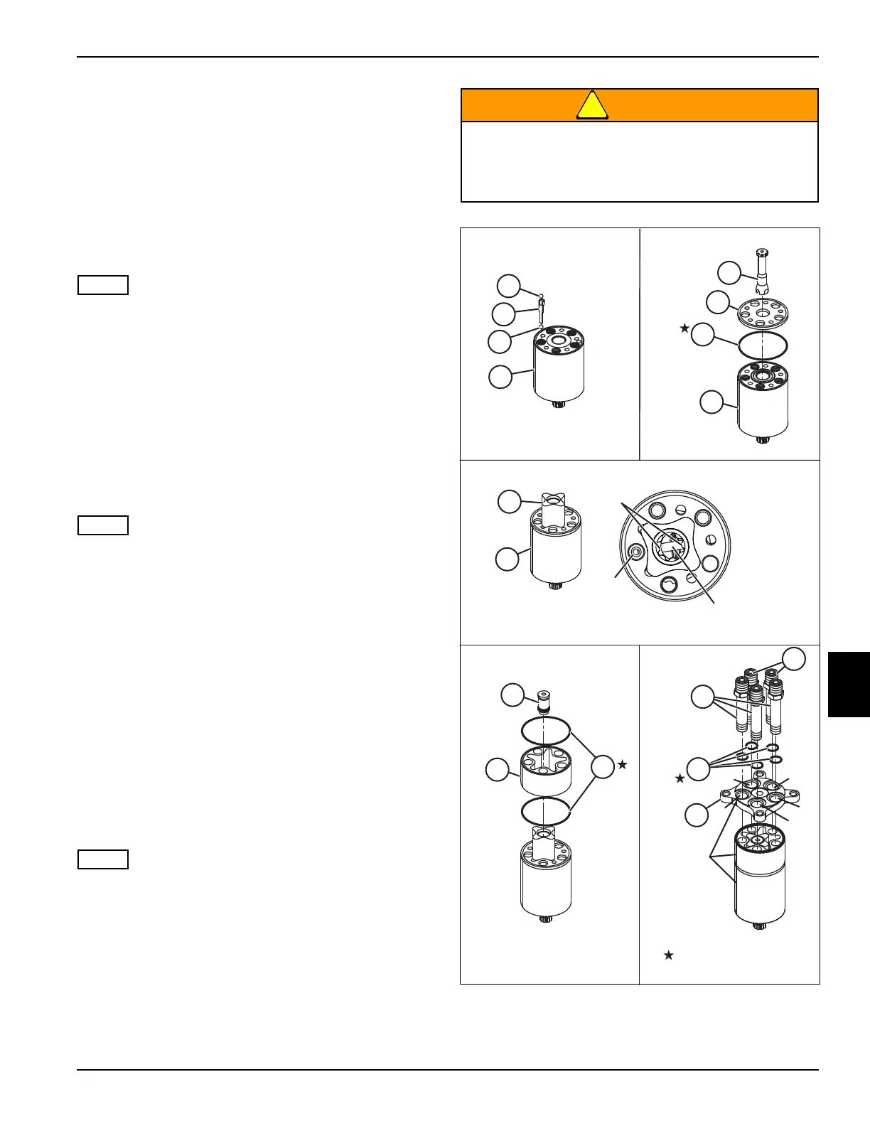
11. Place emergency steering ball (23) in port “P.”
12. Place ball stop (22) in port “P.”
13. Place check valve ball (21) in port “P.”
14. Install O-ring (11) in housing (24).
15. Place distributor plate (9) on housing (24) and align
scribe line and mounting holes.
16. Assemble cardan shaft (10) to spool (16) ensuring
cardan shaft engages with cross pin (13).
17. Place gearwheel (7) over the distributor plate (9).
See step 17 in Figure 7-24. When installing the
gearwheel, the gearwheel must be correctly aligned so
that it engages with the cardan shaft. The cross pin (13)
in the spool assembly must line up with the bottom of the
spline in the gearwheel (7).
18. Install O-rings (6) into groove on each side of the
gearwheel rim.
19. Place gearwheel rim (8) over the distributor plate (9)
and gearwheel (7). Align scribe line and mounting
holes.
20. Install spacer (5) over the cardan shaft (10).
• Place end cover so that the hole marked “P” lines up
with port “P” in the housing.
• Mowers with 3WD option have three -6 ORFS special
screws (1) and two -4 ORFS special screws (2). The
-4 ORFS special screws must be installed in the “L”
and “R” ports.
• Mowers with 4WD option have five -6 ORFS special
screws (1). All five screws are the same and can be
installed in any port.
21. Using scribe line, align end cover (4) to housing (24).
Install special screws (1) with O-rings (3) into ports
“T,” “P,” and “E.” Install special screw (2) with O-ring
(3) into ports “L” and “R.” Tighten screws in an
alternating pattern to 20–24 lb-ft (27–33 N·m).
22. Remove the steering unit from the service fixture.
23. Assemble steering unit into mower.
Do not tighten steering column mounting hardware until
steering relief pressure has been set. Column must be
removed when adjusting relief valve.
24. Set steering unit relief pressure. (See “Lift/Steering
Relief Valve Adjustment” on page 6-44.)
Figure 7-24
Keep hands and arms clear of steering wheel on
initial startup of engine. Steering unit can
become a hydraulic motor if step 17 is not
correctly performed.
R
L
P
T
1
2
3
4
5
6
7
8
9
9
10
11
21
22
23
24
24
Spline
Bottoms
Port
“P”
Cross
Pin
P
E
T
R
L
Scribe line
aligned with
port “P”.
Included in Seal Kit
Steps 14-16Steps 11-13
Step 21Steps 18-20
Step 17

 Loading...

