CUTTING UNITS
673831-Rev A 8-25
8
Disassembly, Inspection, and Assembly
See Figures 8-17 and 8-18.
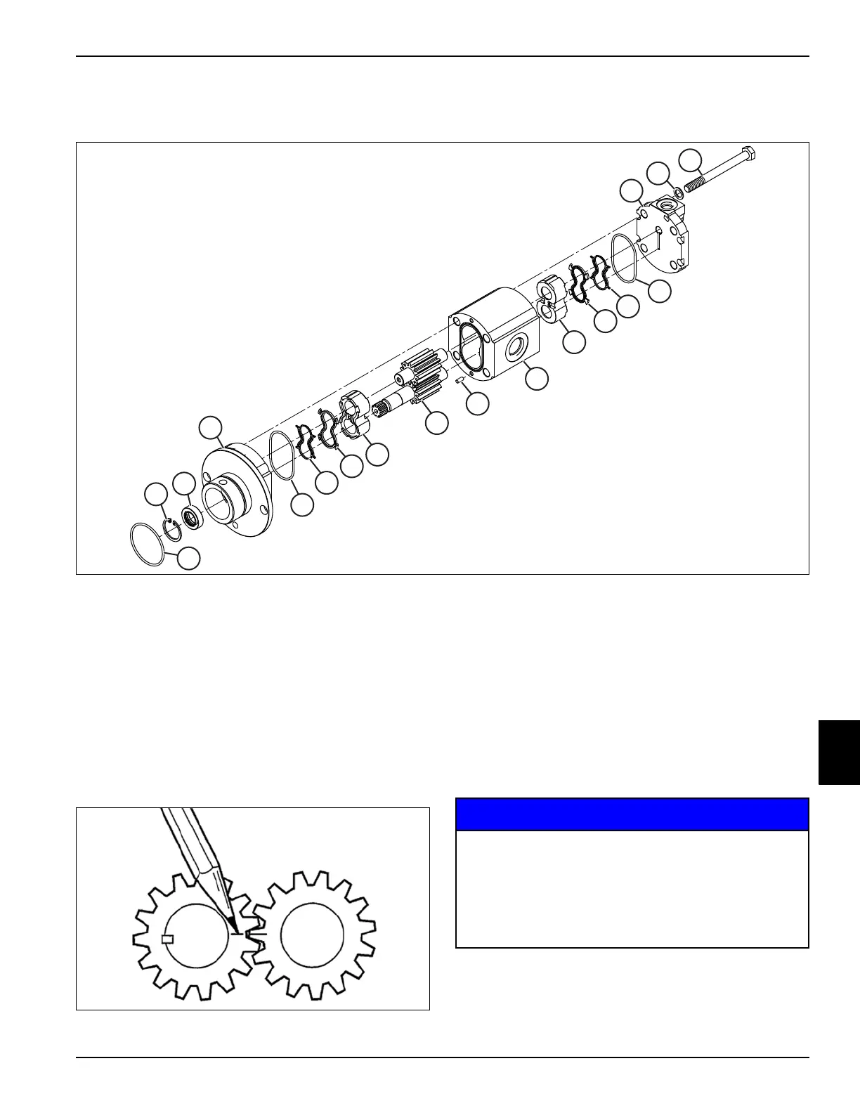
Figure 8-17
Disassembly Notes
• Do not disassemble reel drive motor for repair unless
test procedures indicate internal leakage.
• Never pry components apart. Use a soft-faced
hammer, and gently tap body and drive shaft to
separate reel drive motor body.
Figure 8-18
1. Before removing gear set, mark a line across
meshing teeth to ensure that gears are reassembled
in the same position.
2. Place parts in assembly order on a clean work area
as they are removed.
3. Discard seals as they are removed.
4. Clean all parts using clean solvent, and dry using
compressed air.
1 Mount O-Ring 6 Upper Seal 11 Anti-Extrusion Ring 16 Rear Cover
2 Snap Ring 7 Thrust Plate 12 O-Ring 17 Washer (4)
3 Shaft Seal 8 Gear Set 13 Dowel Pin (4) 18 Retaining Screw (4)
4 Front Cover 9 Thrust Plate 14 Body
5 Anti-Extrusion Ring 10 Seal 15 O-Ring
1
2
3
4
5
6
7
8
9
10
11
12
13
14
15
16
17
18
• It is important that all component parts are
absolutely clean, as contamination can result
in serious damage and/or improper operation.
• Never use shop towels or rags to dry parts
after cleaning, as lint may clog passages. Dry
parts using compressed air.

 Loading...

