4st 25/30 2022
ii
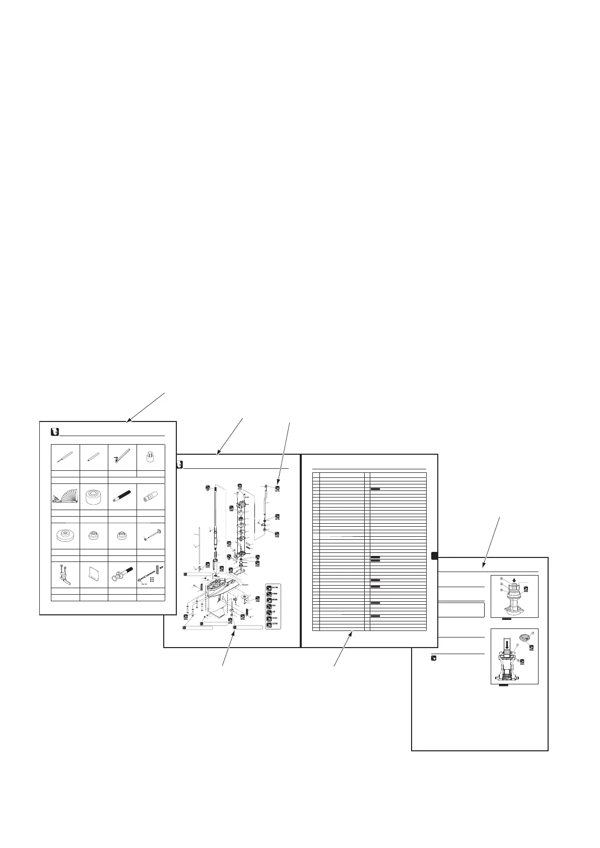
About this manual
Composition and use of this manual
This service manual is designed so that service persons are able to perform repairs correctly.
Understand the following matters well for efficient service and repair.
1 Each chapter begins with the introduction of special tools that are used for the work described.
2 Parts that are serviced in each chapter and their details are presented by using a component composition
diagram.
3 Fastening torques are described in the component composition diagram. In the body text are critical
points of the applicable work.
4 Pictograms indicate that there is an important work instruction for the relevant parts. It also shows the type
of lubricant and its application point(s).
5 The component composition diagrams describe the names of the parts, the number of pieces of the parts
used, size of fasteners and special notes.
6 Specific works are described in detail by using illustrations and adding advice on the work.
6
6-20
4st 25/30 2020
Lower Unit
3. Install the ball bearing 4.
Use the C gear bearing press tool 5 to assemble a new
bearing to the propeller shaft housing.
•
Clean the bearing installation surface and apply
gear oil before installation.
•
Install the bearing with the mark facing the tool
side.
•
Clean the bearing installation surface of
the bevel gear C and apply gear oil before
installation.
•
Use a mandrel that contacts the inner face of
the bevel gear (not the clutch face).
O
I
L
GEARGEAR
GEAR
O
I
L
GEARGEAR
GEAR
4 Ball Bearing
Do not reuse.
4 Bearing
Do not reuse.
51.5 mm
23.9 mm
4 . Assemble the bevel gear C 7 to the bearing using a press
and an appropriate mandrel.
C Gear Bearing Press Tool 5:
P/N. 3AC-99905-0
Driver Rod 6:
P/N. 3AC-99702-0
6
6-5
4st 25/30 2022
Ref.
No.
Part Name Q'ty Remarks
1 Gear Case Assy 1
2 Roller Bearing 1
3 Plug 2
4 Gasket 2
Do not reuse.
5 Trim Tab 1
6 Bolt 1
7 Water Strainer 1
8 Screw 1
9 Water Strainer 2
10 Screw 1
11 Nylon Nut 1
12 Nut 1
13 Bevel Gear B 1
14 Drive Shaft Spring Guide 1
15 Drive Shaft Spring 1
16-1 Drive Shaft (S) 1
16-2 Drive Shaft (L) 1
16-3 Drive Shaft (UL) 1
17 Key 1
18 Tapered Roller Bearing 1
19-1 Shim 35-41.9-0.1 1
19-2 Shim 35-41.9-0.15 1
19-3 Shim 35-41.9-0.3 1
19-4 Shim 35-41.9-0.5 1
20 Oil Seal 17-30-9 1
Do not reuse.
21 Pump Case Gasket (Lower) 1
Do not reuse.
22 Pump Case (Lower) 1
23 Dowel Pin 4-10 2
24 Water Seal Rubber 1
25 Water Seal Plate 1
26 Bolt 2
27 Guide Plate Gasket 1
Do not reuse.
28 Water Pump Guide Plate 1
29 Pump Case Gasket 1
Do not reuse.
30 Water Pump Impeller 1
31 Pump Case Liner 1
32 Pump Case (Upper) 1
33 Bolt 4
34 O-ring 2.4-5.8 2
Do not reuse.
35-1 Cam Rod (S) 1
35-2 Cam Rod (L) 1
35-3 Cam Rod (UL) 1
36 Spring Pin 3-12 2
Do not reuse.
37 Clutch Cam 1
38 Water Pipe Auxiliary Mount 1
39 Lock Plate 1
40 Water Pipe Seal (Upper) 1
6-4
Lower Unit
4st 25/30 2022
1
2
3
3
4
4
5
6
7
8
9
9
10
11
12
13
14
15
16
17
18
19
20
21
22
23
24
25
26
27
28
29
30
31
32
33
33
34
34
35
36
36
37
38
39
40
41
42
Fig.10-9
43
44
5 N·m (4 lb·ft) [0.5 kgf·m]
5 N·m (4 lb·ft) [0.5 kgf·m]
19 N·m (14 lb·ft) [1.9 kgf·m]
35 N·m (25 lb·ft) [3.5 kgf·m]
2. Parts Layout
Gear Case (Drive Shaft)
Lower Unit
6-2
1. Special Tools
Spring Pin Tool A
P/N. 345-72227-0
Spring Pin Tool B
P/N. 345-72228-0
Bevel Gear B Nut Wrench
P/N. 346-72231-0
Bevel Gear B Nut Socket
P/N. 346-72232-0
Removing spring pin Installing spring pin Removing and installing bevel gear B nut
Thickness Gauge
P/N. 353-72251-1
Center Plate
P/N. 3VS-99701-0
Driver Rod
P/N. 3AC-99702-0
Roller Bearing Attachment
P/N. 3AC-99710-0
Measuring gaps
Positioning propeller shaft
housing roller bearing
Installing and removing
bearing and oil seal
Installing propeller shaft
housing roller bearing
Bearing Attachment
P/N. 3AC-99905-0
Oil Seal Attachment
P/N. 3AD-99820-0
Oil Seal Attachment
P/N. 3AG-99820-0
Bearing Outer Press Kit
P/N. 3B7-72739-1
Installing bevel gear
C ball bearing
Installing oil seal of
propeller shaft housing
Installing pump case
(lower) oil seal
Bevel Gear Assy A
Installing bearing outer race
Backlash Measuring Tool Clamp
P/N. 3B7-72720-0
Dial Gauge Plate
P/N. 3B7-72729-0
Shimming Gauge
P/N. 346-72250-0
Backlash Measuring Tool Kit
P/N. 3C8-72234-2
Measuring backlash
For installing dial gauge
during backlash measurement
Adjusting height of
bevel gear B
Measuring bevel gear assy A,
bevel gear B backlash
4st 25/30 2022
25
3BJ-72732-0
ø79.5 x ø51.5
ø29.5 x ø16.5ø27.5 x ø15.5
ø51.5 x ø24.5
6
2
1
5
3
4
 Loading...