84
DISPLAYING THE MEASUREMENT RESULT
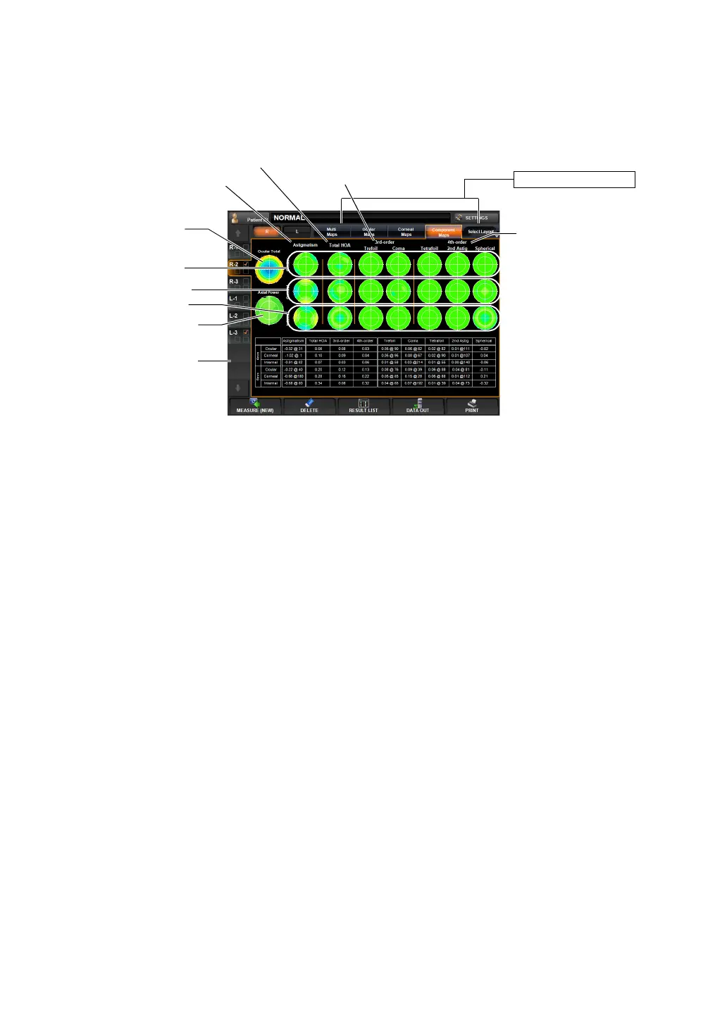
COMPONENT MAP DISPLAY
This map displays the entire eye, cornea, behind the cornea (internal) and important compo-
nents of high order aberration.
In the map, components are tabulated; 3rd-order and 4th-order aberrations are displayed ver-
tically, and ocular, corneal and internal aberrations vertically.
To change display to another map: Tap the Layout Change button.
(1) Ocular total aberration map
(See "Ocular Total Aberration Map" on page 80.)
(2) Axial Power map (See "Axial Power Map" on page 79.)
(3) Astigmatism map Distribution of low order cylindrical refractive power.
Ocular aberration is shown as cylindrical refractive power, and cor-
neal aberration is shown as corneal astigmatic power.
(4) Corneal HOA map (See "Corneal High Order Aberration Map" on page 79.)
(5) Third-order display Third-order aberrations of Zernike coefficient are displayed (Trefoil
and Coma aberration).
Operation: • When tapped, the image is enlarged. (See "ENLARGEMENT DIS-
PLAY" on page 94.)
• The map display step can be changed. (See "SETTING THE
TOTAL ABERRATION MAP DISPLAY STEP (TOTAL ABERRA-
TION MAP RANGE)" on page 146.)
Operation: • When tapped, the image is enlarged. (See "ENLARGEMENT DIS-
PLAY" on page 94.)
Operation: • When tapped, the image is enlarged. (See "ENLARGEMENT DIS-
PLAY" on page 94.)
Operation: • When tapped, the image is enlarged. (See "ENLARGEMENT DIS-
PLAY" on page 94.)
• The map scale can be changed. (See "SETTING THE TOPOMAP
SCALE TYPE (TOPOMAP SCALE - TYPE)" on page 149.)
Layout Change button
(8) Corneal display
(3) Astigmatism map
(6) Fourth-order display
(1) Ocular total
aberration map
(9) Internal display
(2) Axial Power map
(7) Ocular display
(4) Corneal HOA map
(5) Third-order display
(10) Aberration RMS
display