85
DISPLAYING THE MEASUREMENT RESULT
(6) Fourth-order display
Fourth-order aberrations of Zernike coefficient are displayed (Tet-
rafoil, 2nd Astig. and Spherical aberration).
(7) Ocular display Aberration of the whole eyeball obtained from the Hartmann image is
displayed in 3rd and 4th-order.
(8) Corneal display Aberration of the cornea surface obtained from the Placido image is
displayed in 3rd and 4th-order.
(9) Internal display Internal aberration (aberration of whole eyeball minus aberration of
cornea) is displayed.
(10) Aberration RMS display
RMS values (exception: diopter for astigmatism) and angles are dis-
played in analysis diameters (4mm and 6mm). For the direction of
RMS of each order, see "
DESCRIPTION ABOUT RMS DISPLAY OF
CORNEAL ABERRATION" on page 105).
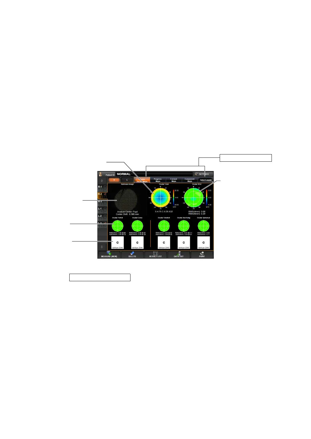
ZERNIKE VECTOR MAP
This map displays important ocular higher order aberrations by components.
To change display: Tap the Select Layout button (at the rightmost of Layout Change buttons),
and tap the
button from the pull down menu.
To change display to another map: Tap the Layout Change button.
(1) Hartmann image (See "Hartmann Image" on page 79.)
(2) Ocular total aberration map(See "Ocular Total Aberration Map" on page 80.)
Operation: • When tapped, the image is enlarged. (See "ENLARGEMENT DIS-
PLAY" on page 94.)
• When dragged in the right-left direction, the overlay can be
changed. (See page
98.)
Operation: • When tapped, the image is enlarged. (See "ENLARGEMENT DIS-
PLAY" on page 94.)
• The map display step can be changed. (See "SETTING THE
TOTAL ABERRATION MAP DISPLAY STEP (TOTAL ABERRA-
TION MAP RANGE)" on page 146.)
Layout Change button
(2) Ocular total aberration map
(3) Ocular HOA map
(5) Simulation
(4) HOA map
(1) Hartmann image
Zernike Vector Map