10.4.3 MOTOR POTENTIOMETER PARAMETERS
The frequency reference of the Motor Potentiometer is available in all the control places. You
can change the motor potentiometer reference only when the drive is in the run state.
NOTE!
If you set the output frequency slower than the Motor Potentiometer Ramp Time,
the normal acceleration and deceleration times give limits to it.
P3.3.4.1 MOTOR POTENTIOMETER UP (ID 418)
Use this parameter to increase the output frequency with a digital input signal.
With a motor potentiometer, you can increase and decrease the output frequency. When you
connect a digital input to parameter Motor Potentiometer UP, and have the digital input
signal active, the output frequency rises.
The motor potentiometer reference INCREASES until the contact is opened.
P3.3.4.2 MOTOR POTENTIOMETER DOWN (ID 417)
Use this parameter to decrease the output frequency with a digital input signal.
With a motor potentiometer, you can increase and decrease the output frequency. When you
connect a digital input to parameter Motor Potentiometer DOWN, and have the digital input
signal active, the output frequency falls.
The motor potentiometer reference DECREASES until the contact is opened.
3 different parameters have an effect on how the output frequency rises or falls when Motor
Potentiometer UP or DOWN is active. These parameters are Motor Potentiometer Ramp
Time (P3.3.4.3), Acceleration Time (P3.4.1.2), and Deceleration Time (P3.4.1.3).
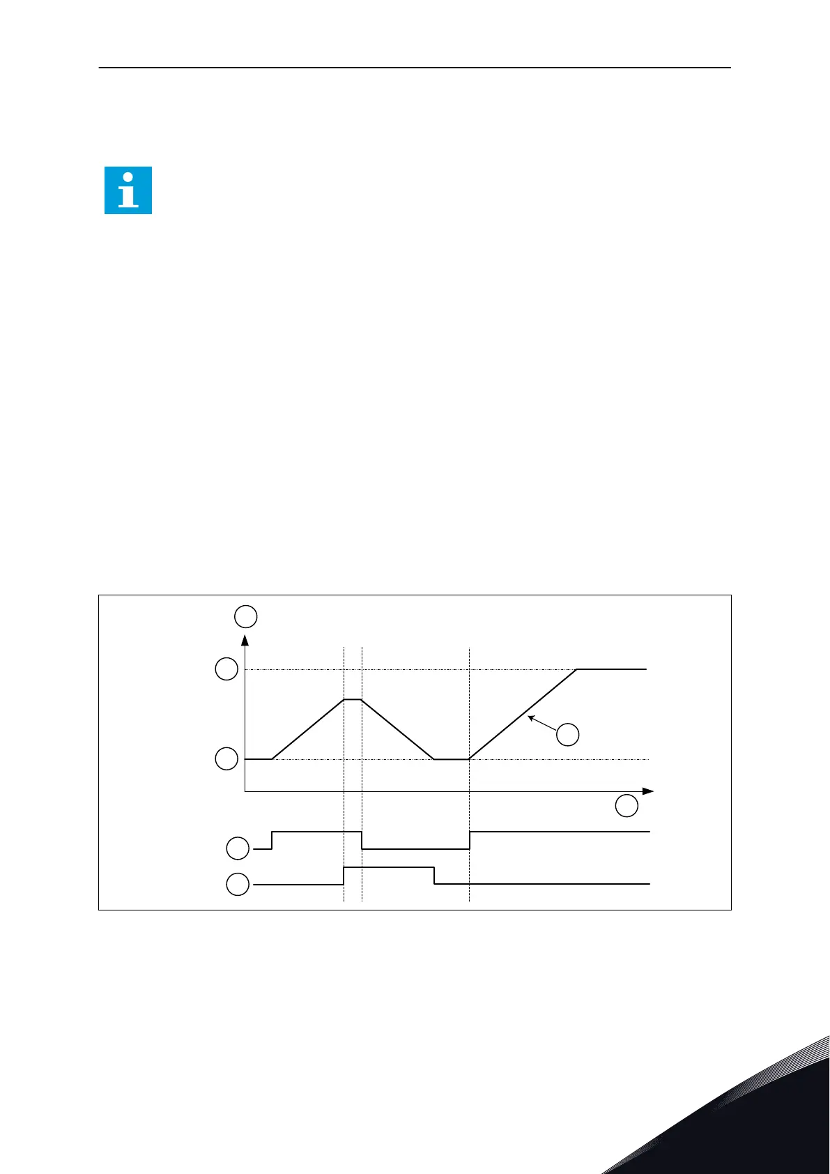
Fig. 48: The motor potentiometer parameters
A. Frequency Reference
B. Max Frequency
C. Min Frequency
D. Motor potentiometer ramp time
E. Time
F. Motor potentiometer UP
G. Motor potentiometer DOWN
PARAMETER DESCRIPTIONS VACON · 245
LOCAL CONTACTS: HTTP://DRIVES.DANFOSS.COM/DANFOSS-DRIVES/LOCAL-CONTACTS/
10

 Loading...