P3.15.22.2 DE-STAGING FREQUENCY (ID 15546)
Use this parameter to adjust the output frequency level at which the auxiliary motor stops in
the Multi-pump system.
NOTE!
The parameter has no effect, if its value is set below Min Frequency Reference
(P3.3.1.1).
By default, an auxiliary pump stops (is de-staged), if the PID feedback signal goes above the
specified bandwidth area and the pump that controls the system operates at the minimum
frequency.
The auxiliary pump can stop at a higher frequency to get better process values or to use less
energy. Then, use the parameter to set the start frequency of the auxiliary pump above the
minimum frequency.
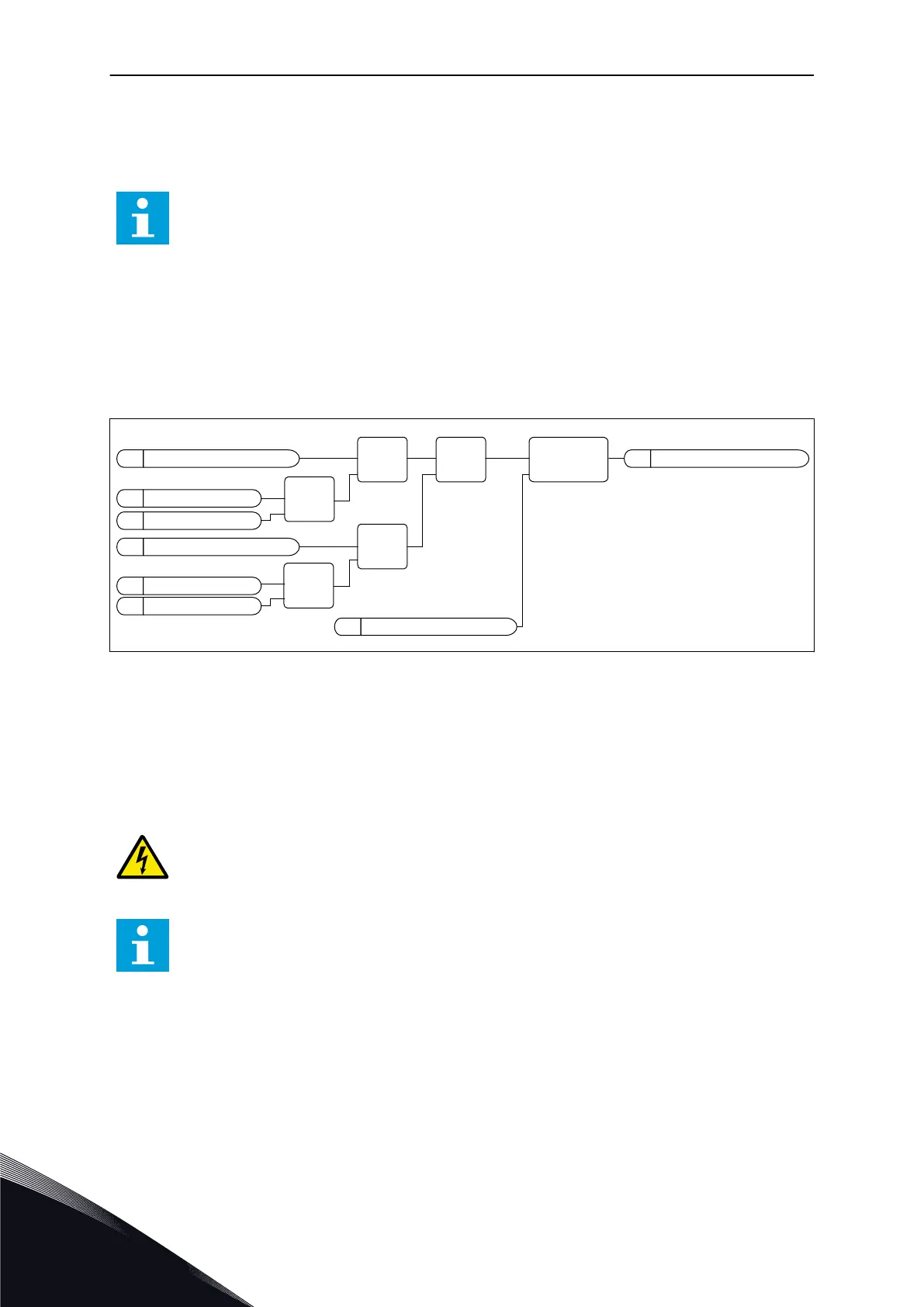
M
PID Feedback
P
Banwidth Delay
Stop Aux Pump
V
M
Output Freq
M
PID Setpoint
P
Freq Ref Min
P
De-Staging Freq
P
Bandwidth
GT
IN1
IN2
LT
IN1
IN2
MAX
IN1
IN2
ADD
IN1
IN2
AND
IN1
IN2
ON-DELAY
IN OUT
TIME
Fig. 103: De-staging frequency
10.17 MAINTENANCE COUNTERS
A maintenance counter tells you that maintenance must be done. For example, it is
necessary to replace a belt or to replace the oil in a gearbox. There are 2 different modes for
the maintenance counters, hours or revolutions*1000. The value of the counters increases
only during the RUN status of the drive.
WARNING!
Do not do maintenance if you are not approved to do it. Only an approved electrician
can do maintenance. There is a risk of injury.
NOTE!
The revolutions mode uses motor speed, which is only an estimate. The drive
measures the speed every second.
When the value of a counter is more than its limit, an alarm or a fault shows. You can
connect the alarm and fault signals to a digital output or a relay output.
When the maintenance is completed, reset the counter with a digital input or parameter
P3.16.4 Counter 1 Reset.
VACON · 342 PARAMETER DESCRIPTIONS
10
LOCAL CONTACTS: HTTP://DRIVES.DANFOSS.COM/DANFOSS-DRIVES/LOCAL-CONTACTS/

 Loading...