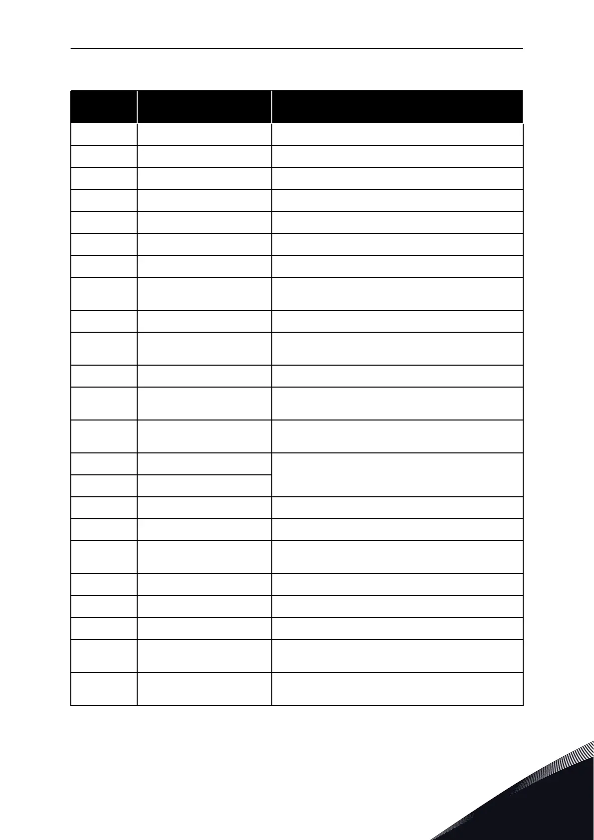
Table 121: The output signals through RO1
Selection
number
Selection name Description
0 Not used The output is not used.
1 Ready The AC drive is ready to operate.
2 Run The AC drive operates (the motor runs).
3 General fault A fault trip occurred.
4 General fault inverted A fault trip did not occur.
5 General alarm An alarm occurred.
6 Reversed The reverse command is given.
7
At speed The output frequency becomes the same as the set fre-
quency reference.
8 Thermistor fault A thermistor fault occurred.
9
Motor regulator activated One of the limit regulators (for example current limit or tor-
que limit) is activated.
10 Start signal active The start command of the drive is active.
11
Keypad control active The selection is keypad control (the active control place is
keypad).
12
I/O control B active The selection is I/O control place B (the active control place
is I/O B).
13 Limit supervision 1 The limit supervision becomes active, if the signal value goes
below or above the set supervision limit (P3.8.3 or P3.8.7).
14 Limit supervision 2
15 Fire mode active The Fire mode function is active.
16 Flushing active The Flushing function is active.
17
Preset Frequency active The selection of preset frequency was made with digital input
signals.
18 Quick Stop active The Quick stop function is activated.
19 PID in Sleep mode The PID controller is in the sleep mode.
20 PID Soft Fill activated The Soft fill function of the PID controller is activated.
21
PID feedback supervision The feedback value of the PID controller is not in the supervi-
sion limits.
22
ExtPID feedback supervision The feedback value of the external PID controller is not in the
supervision limits.
PARAMETER DESCRIPTIONS VACON · 273
LOCAL CONTACTS: HTTP://DRIVES.DANFOSS.COM/DANFOSS-DRIVES/LOCAL-CONTACTS/
10

 Loading...