1
6
2
3
4
5
18
19
30
12
7
13
8
9
10
14
15
16
21
22
23
11
17
A
B
24
25
26
28
29
Modbus RTU
*)
32
33
**)
+
-
A1
A1
A1
A2
A2
A2
mA
Motor 1 control
(Multi-pump K2 contactor)
Motor 2 control
(Multi-pump K2 contactor)
Motor 3 control
(Multi-pump K2 contactor)
AO1-/GND
+24V
in
GND
GND
DI1
DI2
DI3
DI4
DI5
DI6
RO1/1 NC
RO1/2 CM
RO1/3 NO
CM
CM
RS485
RS485
RO2/1 NC
RO2/2 CM
RO2/3 NO
RO3/2 CM
TI1-
TI1+
RO3/3 NO
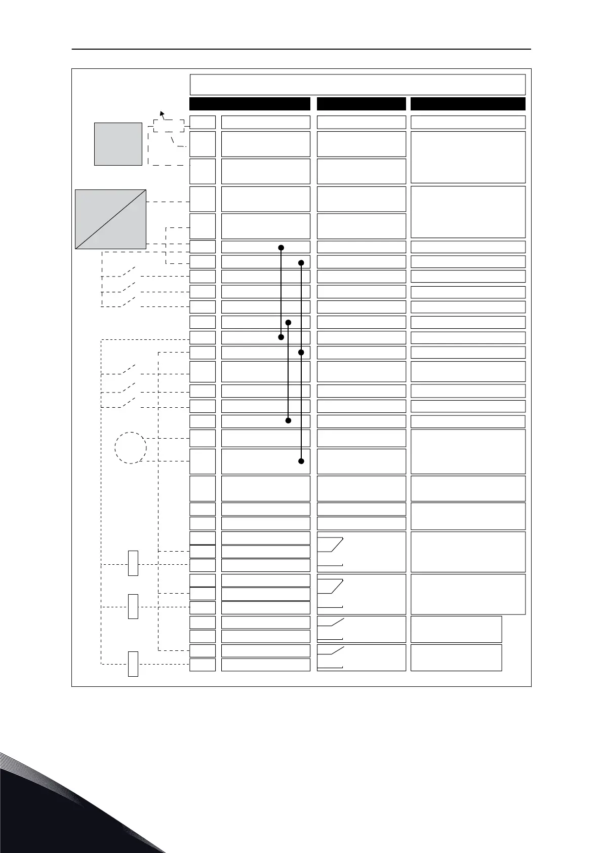
Standard I/O board
Terminal Signal Description
+10V
ref
AI1+
AI1-
AI2+
AI2-
24V
out
Reference output
Analogue input 1 +
Analogue input 1 -
Analogue input 2 +
Analogue input 2 -
24V auxiliary voltage
I/O ground
Digital input 1
Digital input 2
Digital input 3
Digital input 4
Digital input 5
Digital input 6
Common for DI1-DI6
Common for DI1-DI6
24V auxiliary voltage
I/O ground
Analogue output 1 +
Analogue output 1 -
24V auxiliary
input voltage
Output
frequency
( default 0...20mA)
Serial bus, negative
Serial bus, positive
Relay output 1
Relay output 2
Relay output 3
Thermistor input
Control place A/B selection
AO1+
Place A: Not used
Place B: Frequency
reference
(default: 0...10V)
PID feedback
(actual value)
(default: 4...20mA)
Place A: Start forward
(PID controller)
Place B: Start forward
(Freq. ref. P3.3.1.6 )
Reference-
potentiom-
eter
1...10kΩ
I =
(0)4...20mA
Actual
value
2-wire
transmitter
Motor 1 interlock
Motor 2 interlock
Motor 3 interlock
24V
out
Fig. 11: The default control connections of Multi-pump (single drive) application
* = Available only in VACON
®
100 X.
VACON · 34 QUICK STARTUP GUIDE
1
LOCAL CONTACTS: HTTP://DRIVES.DANFOSS.COM/DANFOSS-DRIVES/LOCAL-CONTACTS/

 Loading...