1 +10V ref
2 AI1 +
3 AI1 -
4 AI2 +
5 AI2 -
6 +24V out
7 GND
8 DIN1
9 DIN2
10 DIN3
11 CM
12 +24V out
13 GND
14 DIN4
15 DIN5
16 DIN6
17 CM
18 AO1 +
19 AO1 -
30 +24V in
A RS485
B RS485
21 RO1
22 RO1
23 RO1
24 RO2
25 RO2
26 RO2
32 RO3
33 RO3
0
AUTO MAN
2-WIRE
TRANSMITTER
P
I
PRESSURE
SENSOR 1
1S1
2 4
1
3
Reference voltage
NOT USED
(0...10V)
PID FEEDBACK
(4...20mA)
24V auxilary voltage out
I/O ground
START FORWARD
FLUSHING
(Start Forward + Flushing Freq.)
PID SETPOINT SELECT.
(Open=Keypad SP1, Closed=Keypad SP2)
Common for DI1-DI6
24V auxilary voltage out
I/O ground
FAULT RESET
PUMP INTERLOCK
(Not in use by default)
EXTERNAL FAULT
Common for DI1-DI6
OUTPUT FREQUENCY
(0...20mA)
24V auxilary voltage in
Drive-To-Drive
Communication
(Modbus RTU)
Relay Output 1
(RUN)
Relay Output 2
(FAULT)
Relay Output 3
(READY)
0
AUTO MAN
2-WIRE
TRANSMITTER
P
I
PRESSURE
SENSOR 2
2S1
2 4
1
3
0
AUTO MAN
3S1
2 4
1
3
2-WIRE
TRANSMITTER
P
I
PRESSURE
SENSOR 3
FLOAT
GND
DIO´S
U
I
AI1
U
I
AI2
U
I
AO
OFF
ON
RS485
termination
FLOAT
GND
DIO´S
U
I
AI1
U
I
AI2
U
I
AO
OFF
ON
RS485
termination
FLOAT
GND
DIO´S
U
I
AI1
U
I
AI2
U
I
AO
OFF
ON
RS485
termination
1 +10V ref
2 AI1 +
3 AI1 -
4 AI2 +
5 AI2 -
6 +24V out
7 GND
8 DIN1
9 DIN2
10 DIN3
11 CM
12 +24V out
13 GND
14 DIN4
15 DIN5
16 DIN6
17 CM
18 AO1 +
19 AO1 -
30 +24V in
A RS485
B RS485
21 RO1
22 RO1
23 RO1
24 RO2
25 RO2
26 RO2
32 RO3
33 RO3
Reference voltage
NOT USED
(0...10V)
PID FEEDBACK
(4...20mA)
24V auxilary voltage out
I/O ground
START FORWARD
FLUSHING
(Start Forward + Flushing Freq.)
PID SETPOINT SELECT.
(Open=Keypad SP1, Closed=Keypad SP2)
Common for DI1-DI6
24V auxilary voltage out
I/O ground
FAULT RESET
PUMP INTERLOCK
(Not in use by default)
EXTERNAL FAULT
Common for DI1-DI6
OUTPUT FREQUENCY
(0...20mA)
24V auxilary voltage in
Drive-To-Drive
Communication
(Modbus RTU)
Relay Output 1
(RUN)
Relay Output 2
(FAULT)
Relay Output 3
(READY)
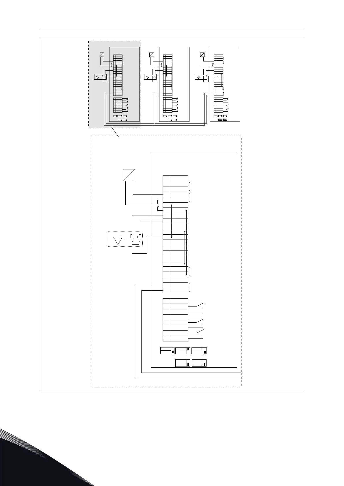
VACON 100 FLOW
P1.2 Application = Multipump(MultiDrive)
P3.15.3 Pump ID Number = 1
P3.15.4 Start & Feedback = Signals Connected
VACON 100 FLOW
P1.2 Application = Multipump(MultiDrive)
P3.15.3 Pump ID Number = 2
P3.15.4 Start & Feedback = Signals Connected
VACON 100 FLOW
P1.2 Application = Multipump(MultiDrive)
P3.15.3 Pump ID Number = 3
P3.15.4 Start & Feedback = Signals Connected
DRIVE 1 DRIVE 2 DRIVE 3
+ -
0
P
I
2
4
1
3
DRIVE 1
VACON 100 FLOW
P1.2 Application = Multipump(MultiDrive)
P3.15.3 Pump ID Number = 1
P3.15.4 Start & Feedback = Signals Connected
2-WIRE
TRANSMITTER
PRESSURE
SENSOR 1
Reference voltage
NOT USED (0...10V)
OUTPUT FREQUENCY
(0...20mA)
PID FEEDBACK (4...20mA)
24V auxilary voltage out
24V auxilary voltage in
I/O ground
I/O ground
FAULT RESET
EXTERNAL FAULT
START FORWARD
Common for DI1-DI6
Common for DI1-DI6
24V auxilary voltage out
PUMP INTERLOCK
(Not in use by default)
Drive-To-Drive
Communication
(Modbus RTU)
Relay Output 1
(RUN)
Relay Output 2
(FAULT)
Relay Output 3
(READY)
FLUSHING
(Start Forward + Flushing Freq.)
PID SETPOINT SELECT.
(Open=Keypad SP1, Closed=Keypad SP2)
DIO´S
FLOAT
GND
U
1
2
3
4
5
6
7
8
9
10
11
12
13
14
15
16
17
18
19
30
A
B
21
22
23
24
25
26
32
33
RO1
RO1
RO1
RO2
RO2
RO2
RO3
RO3
+10V
ref
AI2+
AI1-
AI2+
AI2-
+24V
out
GND
DIN1
DIN2
DIN3
CM
+24V
out
GND
DIN4
DIN5
DIN6
CM
AO1+
AO1-
+24V
in
RS485
RS485
I
U
I
U
I
OFF
ON
AI1
AI2
AO
RS485
termination
AUTO MAN
1S1
Fig. 18: Electric wiring diagramme of the Multi-pump (multidrive) system, example 1A

 Loading...