156
D N E G P
D
FNC
29
1
2
M
3
○ ○ ○○
X Y M S
D.b R.b
KnX KnY
KnM KnS
T C
D,R
V,Z
UnG
K,H
E
" $"
D
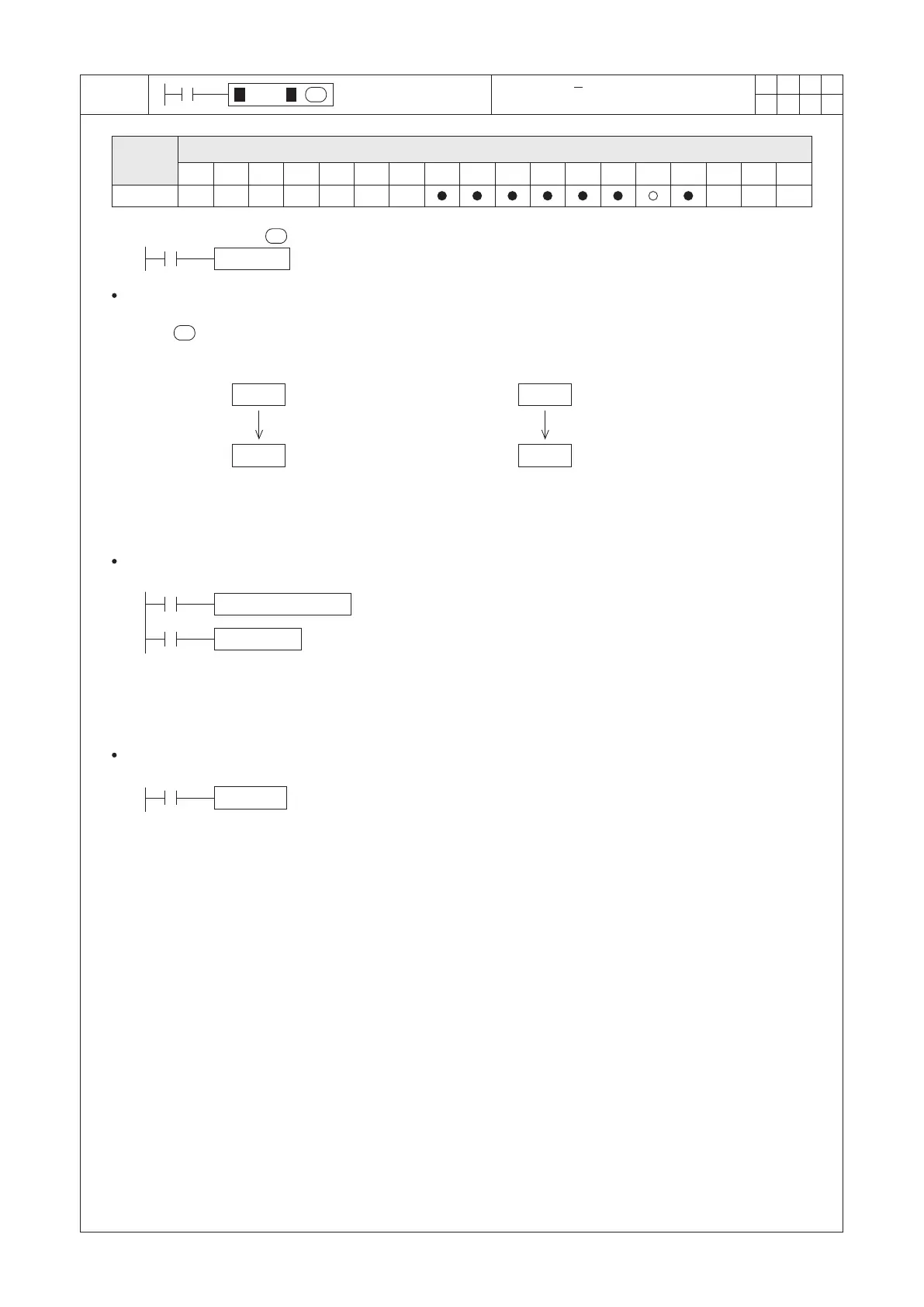
When X20 = “OFF” → “ON”, each single bit pattern of (D0) will be inverted (“0” inverted into “1” and vice versa)
and then added with “1”. The result will be stored in (D0). The instruction selects the complement of “2” for the
value of . The operation changes the positive or negative symbol of a value. For example,
The absolute value of D100 can be generated with the following program.
D : the selected device to be inverted
10
-10
D 0
D 0
X20=OFF→ON
-100
100
D 0
D 0
X20=OFF→ON
BON D100 M0 K15
M9000
NEGP D100
M0
NEGP D0
X20
D
D
NEGP D0
D0.F
th.
If the 15 bit (MSB) of D0 is equal to “1”, it indicates that the content value of D0 is
negative. Therefore, the absolute value of D0 can be generated through opposite.
Operand
Devices
Negation (D)+1 → (D)
Before Execution
After Execution
Before Execution
After Execution
th.
If the 15 bit (MSB) of D100 is equal to “1”, it indicates that the content
value of D100 is negative, where M0 = “ON”; otherwise, M0 = “OFF”.
When M0 = “OFF” → “ON”, we will take a negative value for D100, where the
value of D100 will be inverted into a positive from a negative.
The absolute value of D0 can be generated with the following program.
 Loading...