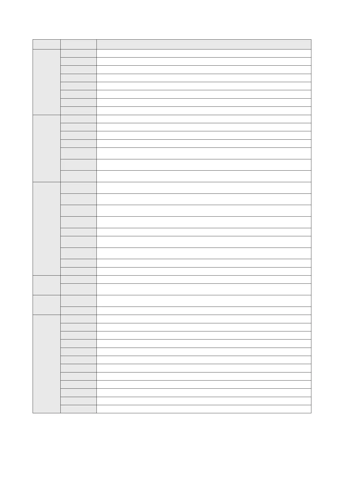
11
VS-1PT-EC
VS-2PT-EC
VS-MC
VS-MCR
VSPC-200A
VSEC- □ □ □
VB-T8R
VB-T8RS
VB-T8M
VB-T16M
VB-T16TB
VBIDC- □ □ □
VBIW- □□ □
VBIDC-FC100
VBIDC-FC250
VB-HT214
VBIDC-HD20
VBIDC-HD100
VS-3AV-EC
VS-4AD-EC
VS-2DA-EC
VS-4A-EC
VS-3ISC-EC
VS-2TC-EC
VS-4TC-EC
★
VS-8XY -EC
VS-8X-EC
VS-8YT-EC
★
VS-4XY -EC
VS-4X-EC
★
VS-4Y -EC
VS-8XI-EC
VS-8YTI-EC
VS-485A-EC
VS-485-EC
VS-D232-EC
VS-D 485A-EC
VS-D 485-EC
Main Specification
Model Name Item
DIO
Expansion
Card
DI Expansion Card: 4 DI (DC 24V); output by screw-clamp terminal
DI Expansion Card: 8 DI (DC 24V); input by screw-clamp terminal
DO Expansion Card: 4 DO ★; output by screw-clamp terminal
DO Expansion Card: 8 DO (DC 24V, 300mA NPN transistor); output by screw-clamp terminal
DIO Expansion Card: 2 DI (DC 24V); 2 DO ★; I/O by screw-clamp terminal
DIO Expansion Card: 4 DI (DC 24V); 4 DO ★; I/O by screw-clamp terminal
DI Expansion Card: 8 DI (DC 24V); input by IDC connector
DO Expansion Card: 8 DO (DC 24V, 100mA NPN transistor); output by IDC connector
RS-485 Communication Expansion Card: One non-isolated RS-485 port with TX / RX indicators; dist. 50m Max.
RS-485 Communication Expansion Card: One isolated RS-485 port with TX / RX indicators; dist. 1000m Max.
RS-485 Communication Expansion Card: Dual non-isolated RS-485 ports with TX / RX indicators; dist. 50m Max.
RS-485 Communication Expansion Card: Dual isolated RS-485 ports with TX / RX indicators; dist. 1000m Max.
RS-232C Communication Expansion Card: Dual non-isolated RS-232 ports with TX / RX indicators;
dist. 15m Max.; wiring by the RX / TX / SG terminals
Special
Function
Card
Comm.
Expansion
Card
Brief Voltage I/O Card: 2 channel (0 ~ 10V, 12-bit) inputs; 1 channel (0 ~ 10V, 10-bit) output; with a calibrated
DC 10V output; non-isolated
Analog Input Card: 4 channel (12-bit) inputs, each channel could output either –10 ~ +10V, 4 ~ 20mA or
–20 ~ +20mA; non-isolated
Analog Output Card: 2 channel (12-bit) outputs, each channel could input either –10 ~ +10V, 4 ~ 20mA or
–20 ~ +20mA; non-isolated
Analog I/O Card: 2 channel (12-bit) inputs + 2 channel (12-bit) outputs, each channel could input/output either
–10 ~ +10V, 4 ~ 20mA or –20 ~ +20mA; non-isolated
Inverter Speed Control Card: 3 channel (0.1% resolution) voltage outputs; totally isolated for each channel
Thermocouple Temperature Input Card: 2 channel (K, J, R, S, T, E, B or N type thermocouple, 0.2 ~ 0.3℃
resolution) inputs; non-isolated
Thermocouple Temperature Input Card: 4 channel (K, J, R, S, T, E, B or N type thermocouple, 0.2 ~ 0.3℃
resolution) inputs; non-isolated
PT-100 Temperature Input Card: 1 channel (3-wire PT-100, 0.1℃ resolution) input; non-isolated
PT-100 Temperature Input Card: 2 channel (3-wire PT-100, 0.1℃ resolution) inputs; non-isolated
Memory
Card
Memory Card: No battery required 16Mb Flash ROM for user's project and data-bank (655,360 words) storage
Multi-Function Memory Card: 16Mb Flash ROM for user's project and data-bank (655,360 words) storage;
with the Real Time Clock function
Connection
Cable
USB Communication Cable: Between the PLC's Mini USB Programming Port and a computer's A-type USB;
length: 200 cm
Extension Cable: For the Expansion Slot of the VS series; length□□□:50/100 cm
IDC
Connector
Related
Accessory
8 Relays Output Module: 16A 1c contact relays; with varistors and relay sockets
8 Relays Output Module: 5A 1a contact relays; with 5mm removable screw-clamp terminals
8 MOSFETs Output Module: 2A current source MOSFETs; with yback diodes
16 MOSFETs Output Module: 2A current source MOSFETs; with yback diodes
16 Points Adapted Board: Transfer between the IDC connectors and screw-clamp terminals
IDC Ribbon Cable: Assembled with two 10-pin female connectors; length□□□:50/100/150/200/250/300 cm
IDC Dispersed Wires: An IDC female connector with 10 rainbow 22 AWG wire; length□□□:50/100/200/300 cm
10-pin Ribbon Cable: Flat, Grey, 28 AWG; length: 100 foot
10-pin Ribbon Cable: Flat, Grey, 28 AWG; length: 250 foot
10-pin IDC Connector: Female connector with strain relief, Grey, 20 pcs.
10-pin IDC Connector: Female connector with strain relief, Grey, 100 pcs.
A crimping tool of IDC ribbon cable
★ Selectable output:
R: 2A Relay;
T: 0.5A NPN transistor (EC cards are 0.3A), at Y0~3 could generate purse (VS1/2: 50kHz; VSM/3: 200 kHz);
P: 0.5A PNP transistor, at Y0~3 could generate 1kHz purse
All Main Unit, Special Module and IDC's module are required DC 24V -15% / +20% power input
VS-D52A-EC
RS-485 + RS-232C Communication Expansion Card: One isolated RS-485 port (1000m) &
one non-isolated RS-232C port (15m), both with TX / RX indicators and wiring by terminals
VS-ENET-EC
Ethernet + RS-485 Communication Expansion Card: One Ethernet port (with additional non-isolated RS-485, dist.
50m) & one non-isolated RS-485 port (dist. 50m), both with TX / RX indicators