180
FNC
52
1
2
M
3
○○○○
M T R
n
D1 D 2
S
X Y M S
D.b R.b
KnX KnY
KnM KnS
T C
D,R
V,Z
UnG
K,H
E
" $"
S
D1
n
D2
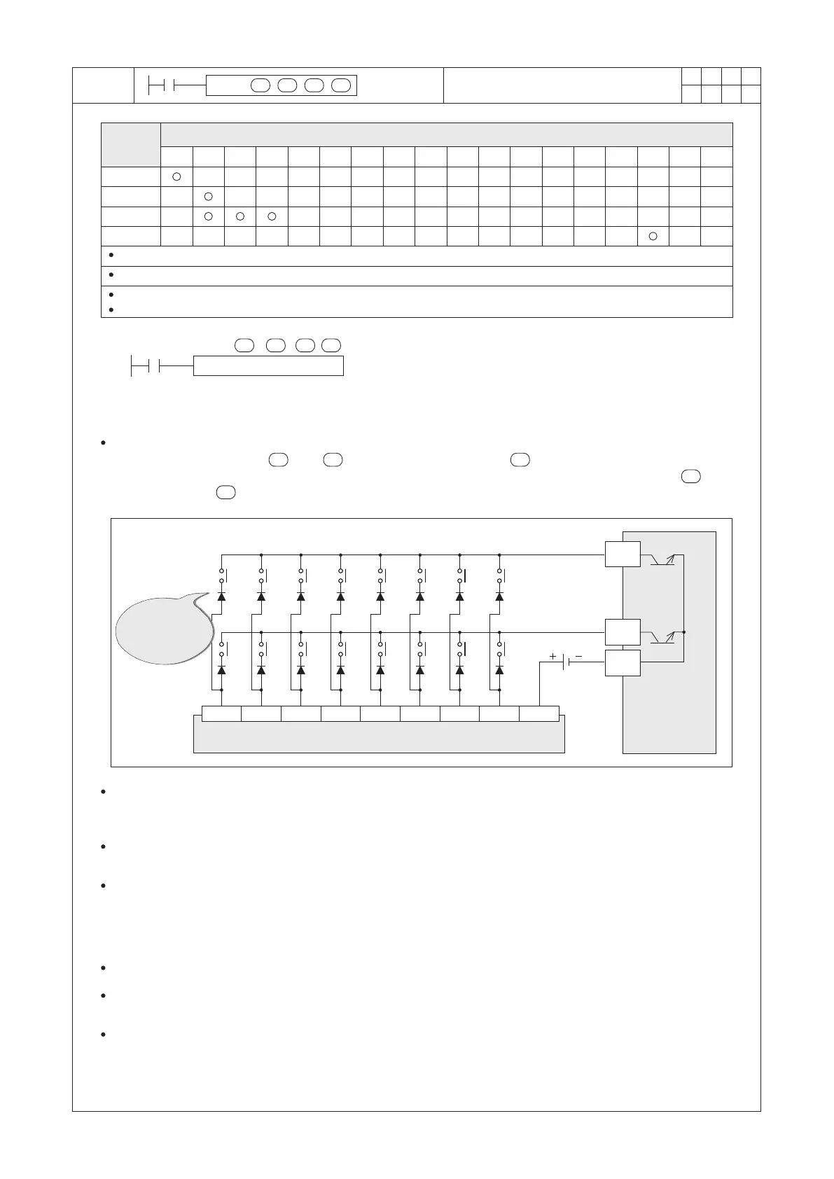
MTR X20 Y20 M0 K2
X0
PLC’s input points
M11 M12 M13 M14 M 15 M16 M17
M0 M1 M2 M3
M4 M 5
M6
M7
Y21
Y20
COM
DC24V
X20
X21 X22
X23
X24
X25 X26
X27
S/S
M10
PLC’s transistor
output points
S
D1 D 2
n
This instruction reads the status of switches through the matrix scan technique. It needs to use consecutive 8
inputs (which are headed by ) and outputs (which are headed by ). By the sequential outputs to scan
and read the status of inputs, then the result is reflected in the storage components which are headed by .
Therefore, total 8× of the external “ON”/“OFF” status are received.
n
S
D1
n
D2
A 0.1 A/ 50 V
diode should be
serially connected
here
Operand
Devices
Input Matrix
S should designate to an X with the last digit of the ID is “0” (e.g. X0, X10), S occupies consecutive 8 points.
D1 should designate to a Y with the last digit of the ID is “0”(e.g. Y0, Y10), D1 occupies consecutive n points.
D2 should designate a Y, M or S with the last digit of the ID is “0”(e.g. Y0, M10, S20), D2 occupies consecutive (8×n) points.
n=2~8
S : the head point for the matrix scan inputs
D1 : the head point for the matrix scan outputs
D2 : the head point of the result matrix-table
(storage components)
n : the number of array rows of the matrix scan
External Wiring Diagram of the Input Matrix
From the diagram above, X20~X27 and Y20~Y21 constitute two rows of array matrix input circuit. When X0=“ON”,
the instruction is ready for execution then 16 (8×2) “ON”/ “OFF” statuses at the array matrix will be read and stored
in the components of M0~M7 and M10~M17.
When X0=“OFF”, the instruction is inactive and the statuses of M0~M7 and M10~M17 will remain as same as the
statuses before it is disabled.
Using the MTR instruction to read one row of the external array switches will take two Scan Times. If the PLC’s
Scan Time is less than 10ms, then one row in the array will spend 20ms to read the “ON”/ “OFF” status of external
inputs. Since this instruction can connect at most 8 of array rows to read 64 (8×8=64) external switches, to reload
that once will take 16 Scan Time or 160ms. Therefore, the coordination between the response rate of external
switches and the loading time of the instruction should be considered when this instruction is used.
Usually, the instruction’s conditional contact uses the M9000 (permanently “ON”, “a” contact).
When this instruction performs to scan and reload status once, it will let the Execution Completed Flag
M9029=“ON” for one Scan Time.
The MTR instruction can only be used once in the program and should appoint to a transistor output unit.

 Loading...