179
FNC
51
1
2
M
3
○○○○
R E F F P
n
n
X Y M S
D.b R.b
KnX KnY
KnM KnS
T C
D,R
V,Z
UnG
K,H
E
" $"
n
=0~60
n: the setting for response time (unit = ms)
Response time of the external inputs X0~X7 is set up by the content value of D9020;
could use the MOV instruction to load a new response time to the D9020.
By the data at the buffer of 0 ms response time digital lter to renew the external
inputs X0~X7 and store that to the input data memory.
Even the response time of the external input X0~X7 digital filter is adjusted to 0 ms,
actually there is still having a few to dozens of µs response time delay.
By the data at the buffer of 20 ms response time digital lter to renew the
external inputs X0~X7 and store that to the input data memory.
The response time of the external input X0~X7 is adjusted to 20 ms.
When the interrupt function, the high speed counter or the SPD (FNC56) instruction is used in the program, the
response time of the corresponding input terminal will be automatically adjusted to 0 µs. However, there is still
having a few to dozens of µs response time delay.
REFF K0
REFF K20
END
M9000
M9000
Program’s step 0
REFF K1
X20
n
Input Point
Digital Filter
Buffere
Can use the MOV
instruction to set the
value.
To select and renew
the status from one
digital filter buffer
which corresponds
to the response set
time.
Input data memory
When the PLC’s power
is turned form “OFF” to
“ON” or the END
instruction is performed.
When the PLC’s power
is turned “OFF”→“ON”,
D9020=10 (default).
X0
X7
0ms
1ms
10ms
11ms
60mS
0
1
10
11
60
D9020
When the REFF instruction is performed, the set time
for the instruction will be loaded.
n
3
2
1
〜〜〜
Operand
Devices
I/O Refresh and Filter Adjust
When X20=“ON”, response time of external inputs X0~X7 will be changed into 1ms and the “ON”/“OFF” statuses
of X0~X7 will be reloaded into the input data memory.
To avoid noise intervention, usually there will be a lter with response time of approximately 10ms on the PLC’s
input point to lter out noise; Therefore, it is unable to capture a rapid input signal that width is less than 10ms.
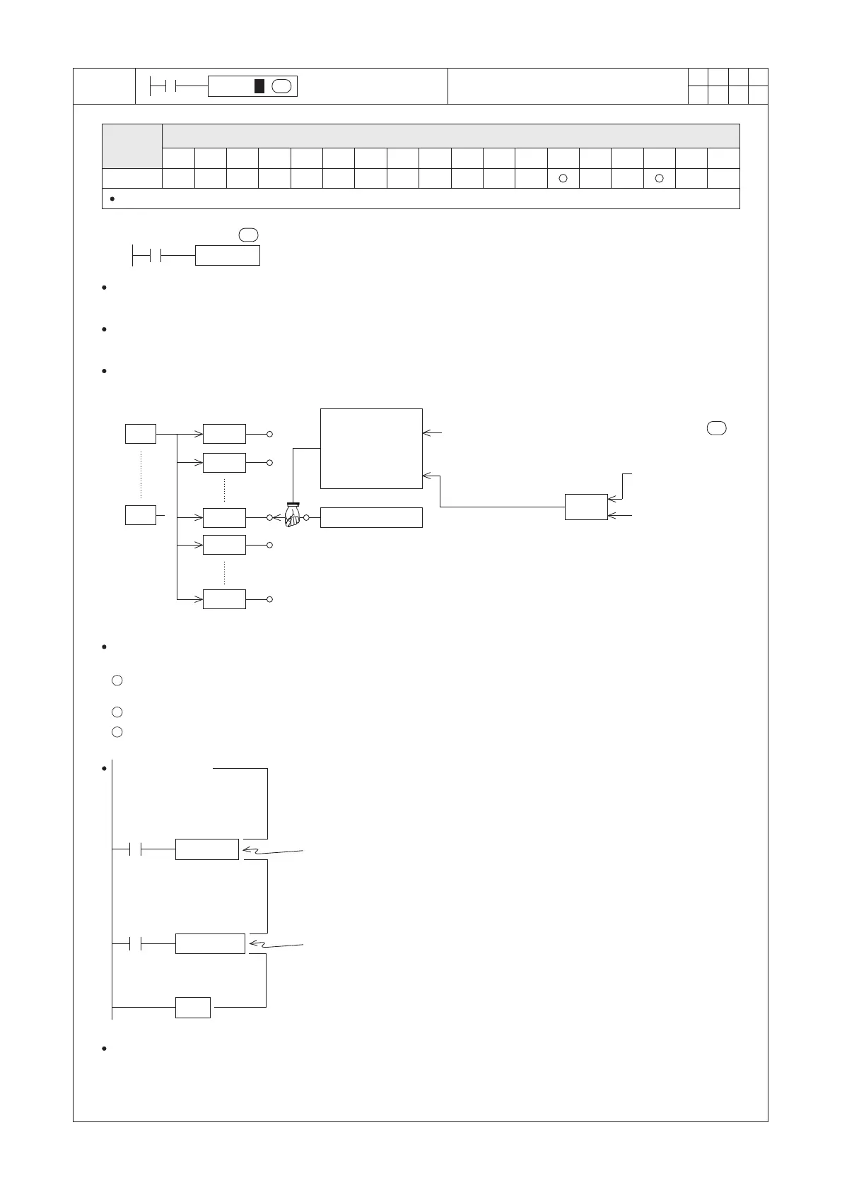
The external inputs X0~X7 are equipped with software digital lters on, which we can use the REFF instruction to
adjust response time. The following gure shows the input conguration of X0~X7:
As shown in the gure above, the external inputs X0~X7 have built-in digital lters with 0~60 ms adjustable range.
The rules to set the response time of input contacts X0~X7 are described as follows:
When the PLC’s power is turned form “OFF” to “ON”, the content value of D9020 will be set to 10 and response
time will be set to 10ms.
Could adjust the response time by using the MOV instruction to load a new value to the D9020.
Use the REFF instruction to adjust the response time during the program is in execution.

 Loading...