190
FNC
59
1
2
M
3
○○○○
D P L S R
S1
S2
D
S3
X Y M S
D.b R.b
KnX KnY
KnM KnS
T C
D,R
V,Z
UnG
K,H
E
" $"
S1
D
S2
S3
PLSR K1000 D100 K1000 Y0
X20
D
S1
S2
S3
S1
D=Y0~Y3
S2=1~2,147,483,647 S3=0~5,000
S2
S3
S1
S1
S2
S3
S3
D
S1
S2
S3S3
X20
M9340
M9341
M9342
Operand
Devices
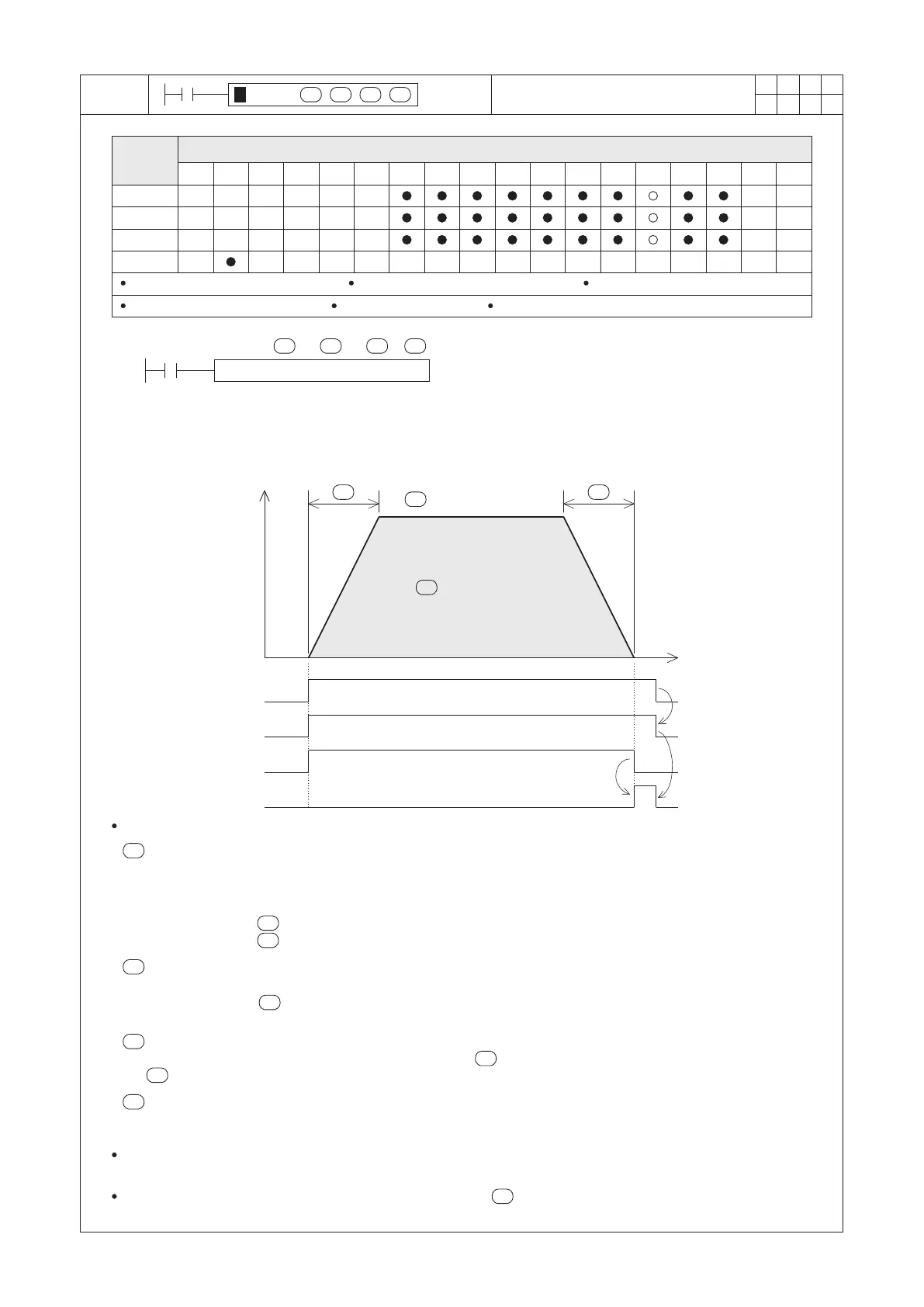
Pulse Ramp
VS1 / VS2 series S1 = 1~50,000 VS2 / VS3 series S1 = 1~200,000 VSM-28ML S1 = 1~1,000,000
S1 : the target frequency of output pulses
S2 : the number of total output pulses
S3 : the ramp time for acceleration or deceleration
(unit: ms)
D : the pulse output point
Pulse
frequency
(Hz)
Time
The acceleration /
deceleration time
S1
the target frequency
of output pulses
the number of total
output pulses
The acceleration /
deceleration time
When X20 = “ON”, Y0 will output the specied pulses by the content value of D100 as the diagram above.
designates the target frequency of output pulses.
At the VS1 & VS2 series, the available target output frequency is from 1 to 50,000Hz.
At the VSM & VS3 series, the available target output frequency is from 1 to 200,000Hz.
At the VSM-28ML, the available target output frequency is from 1 to 1,000,000Hz.
When the value of is less than 1, it will be treated as 1.
When the value of is larger than the range, it will be treated as the maximum value.
designates the number of total output pulses.
It can specify the range from 1 to 2,147,483,647 pulses.
When the value of is less than or equal to 0, the PLC will regard it as an operating error and the M9067
will be “ON”.
designates the ramp time for acceleration or deceleration (unit = ms).
The available range is from 0 to 32,000. If the value of is less than 0, it will be treated as 0; if the value of
is larger than 32,000, it will be treated as 32,000.
designates the pulse output point.
It can only designate to the point Y0~Y3 to be the pulse output device and must use a transistor main unit.
When the condition contact X20 turns “OFF” during pulse output, the output frequency will gradually slow down
then stop.
During this instruction is being executed, the content value of can be altered by the program to change the
frequency; Changes in other parameters will be treated as invalid.
 Loading...