D T K Y
D1 D 2
S
1
2
M
3
○○○
FNC
70
X Y M S
D.b R.b
KnX KnY
KnM KnS
T C
D,R
V,Z
UnG
K,H
E
" $"
S
D1
D2
TKY X20 D0 M0
X0
9
2
1
0
X20
X21
X22
X31
S/S
DC24V
1 0
3
1 0
2
1 0
1
1 0
0
BCD
BIN
D0
9
2
1
0
X20
X21
X22
X31
M0
M1
M2
M9
M10
D2
S
D1 D2
S
D1
1
2
3
4
1
2
3 4
○
Operand
Devices
Ten Key Input
S occupies 10 components
D2 occupies 11 components
D1 : to place where the key input value is stored
D2 : the initial destination device of the keys' status outputs
S : the initial device of the key input
The instruction designates consecutive ten input devices and those are starting from , therefore each one of
the input is to represent a decimal number 0~9 in order. Since these 10 external input devices are connected to
10 keys and these are pressed in sequence, a four-digit decimal number 0~9,999 (a 16-bit instruction) or an
eight-digit decimal number 0~99,999,999 (a 32-bit instruction) can be input, then the input value will be placed in
. Also the instruction occupies 11 consecutive devices which starting from will be used to store the status
of the keys.
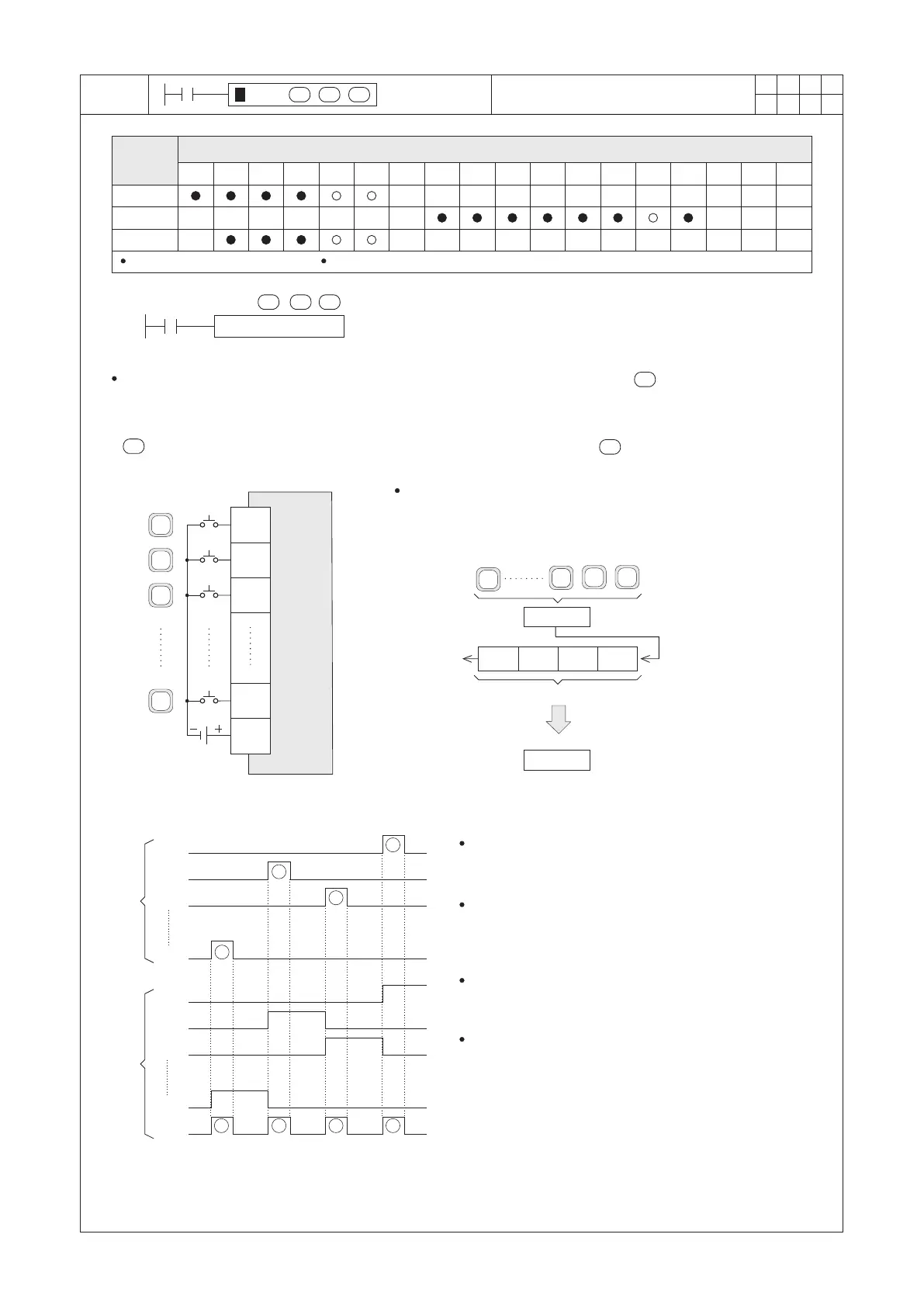
As in the left diagram, the input points X20~X31 are received the
signals from keys 0~9. When X0= “ON”, the instruction starts to
be performed. The value input by the number keys is placed in D0
(by format of BIN) and the statuses of the keys are restored in
M0~M9 and M10.
Input
points
of a PLC
Key
One-Digit of BCD Code
Overflow
Number Keys
BCD Value
BIN Value
Key Input Signals Keys' status outputs
As shown in the left sequence diagram, the number keys
and the related X20~X31 are input in order ① ② ③ ④
then the result 9,120 is stored in D0.
When X31 is triggered (key #9 is pressed), M9 will turn
“ON” and remain “ON”, until the next key is pressed
(when the X21=“ON” → M9=“OFF”). The same
situation applies to other keys.
If any of the keys for the X20~X31 is pressed,
M10=“ON” at the moment and the corresponding
device M0~M9 will be turned “ON”.
When the status of X0 “ON” → “OFF”, the value of D0
will remain but the M0~M10 will all turn “OFF”.
206

 Loading...