207
D H K Y
D1 D 2
S
D3
1
2
M
3
○○○
FNC
71
X Y M S
D.b R.b
KnX KnY
KnM KnS
T C
D,R
V,Z
UnG
K,H
E
" $"
S
D1
D2
D3
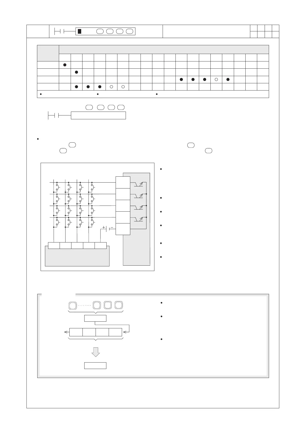
HKY X20 Y20 D0 M0
X0
A B
C
D E F
1
2
3
4
5
6
7
0
8
9
DC24V
Y23
Y22
Y21
Y20
COM
S/S
X20
X21 X22
X23
S
D1
D3D 2
S
D1
D3D2
○
Operand
Devices
Hexadecimal Key Input
S occupies 4 components
D1 occupies 4 components D3 occupies 8 components
D1 : multiplex scanning initial point of the outputs to the keyboard
D2 : to place where the keyboard input value is stored
S : multiplex scanning initial point of the inputs from the keyboard
D3 : the initial destination device of the keys' status outputs
The instruction creates the Hexadecimal Keyboard Input by matrix scan of 4 consecutive external input points
initiating from and 4 consecutive external output points initiating from . The value input by the keyboard is
stored in . And the instruction uses 8 consecutive devices which starting from to store the status of the
keys.
Hexadecimal Keyboard
Circuit Diagram
Transistor
output
points
of the PLC
Input points of the PLC
In the left diagram, the Hexadecimal Keyboard is
connected with X20~X23 and Y20~Y23. When
X20= “ON”, the instruction is active.
The value input by the keyboard is placed in D0 and
the status of those keys are restored in M0~M7.
M9029 will turn “ON” for a Scan Time when the
instruction is performed for a scan.
If there are several keys being pressed at the same
time, only the first key activated is effective.
If the special coil M9167 is already ”ON”, the HKY
instruction can be used for input a hexadecimal
value 0 ~ F.
The HKY instruction can be used once only in the
program.
This instruction is only recommended for use with
transistor output model.
BCD
BIN
D0
9
2
1
0
1 0
3
1 0
2
1 0
1
1 0
0
Number Input
Number Keys
One-Digit of BCD Code
Overflow
BCD Value
BIN Value
The value input by the number keys is placed in
D0 (by format of BIN).
For a 16-bit instruction, the available maximum
input value will be 9,999. If an input value has
more than 4 digits, the previous digit will be
overflowed.
For a 32-bit instruction, the available maximum
input value will be 99,999,999.
If an input value has more than 8 digits, the
previous digit will be overflowed.


 To Next Page