D S W
n
D1 D 2
S
1
2
M
3
○○○
FNC
72
X Y M S
D.b R.b
KnX KnY
KnM KnS
T C
D,R
V,Z
UnG
K,H
E
" $"
n
n=1~2
S
D1
D2
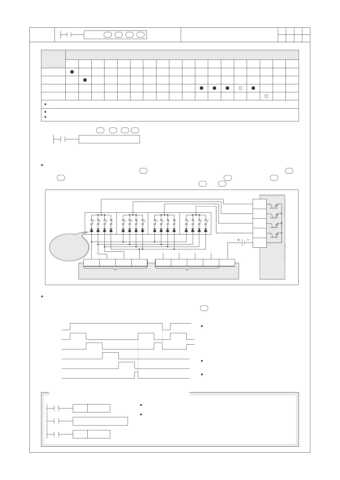
DSW X20 Y20 D0 K1
X0
S : the initial input point of multiple scans from the digital switch
D1 : the initial output point of multiple scans to the digital switch
D2 : to place where the switches' input value is stored
n : the number of digital switch sets is connected
The instruction reads one set (or two sets) of four-digit thumbwheel switches by 4 (or 8) consecutive input points,
those consecutive inputs are starting from . Also, it uses 4 output points to scan which are starting from .
X23
X22 X21
X20
8
4
2 1
DC24V
Y23
Y22
Y21
Y20
COM
X22 X21
X20 X27
X26 X25
8
4
2 1
X24
S/S
10
3
10
2
10
1
10
0
The left diagram is the DSW's scan
sequence. When X0= “ON”, Y20~Y23
will automatically cycle the scan. If each
cycle is completed, the Execution
Completed Flag M9029 will “ON” for a
Scan Time.
Better use a transistor output unit for the
multiplex scan outputs Y20~Y23.
The instruction can only be used once in
the program.
X0
Y20
Y21
Y22
Y23
M9029
SET
DSW X20 Y20 D0 K1
M0
X0
M0
M9029
RST
M0
S
D1 D 2
n
S
D1
D2
n
○
209
When n = 1, S occupies 4 components and D1 occupies 4 components, D2 occupies 1 components
When n = 2, S occupies 8 components and D1 occupies 4 components, D2 occupies 2 components
Digital Switch (thumbwheels) input circuit diagram
PLC's inputs for the set #1
Here must have
serial connected
diodes
(0.1A 50V)
Transistor
output
points
of the PLC
PLC's inputs for the set #2
Operand
Devices
0.1 Sec
0.1 Sec
0.1 Sec
0.1 Sec
0.1 Sec
0.1 Sec
The diagram shown above is a circuit of a multiplexed 4 thumbwheels switch which is composed by X20~X23 and
Y20~Y23. When X0= “ON”, the instruction will start to be performed, the value of the thumbwheels will be read
and converted into a BIN format then the value will be stored in D0. If =K2 and input points X24~X27 are
nd
connected with another set of the thumbwheels then the value of the 2 set of the thumbwheels will be stored in D1.
n
Digital Switch (Thumbwheel) Input
X0 uses the push-button switch.
The DSW instruction will read the value of the thumbwheel switch
once when X0 is triggered. At the rest time, the DSW instruction is
inactive and not to scan. Therefore, could reduce the scan
problem at the relay output.
The Method of Using the Relay Output Unit for the Scan
If the = K1, it reads up one set of digital switch and puts a four-digit value to ; besides, If the = K2, it
reads up two sets of digital switches and puts two four-digit values to and +1.
n
D2 D 2
 Loading...