211
S E G L
D
n
S
1
2
M
3
○○○
FNC
74
X Y M S
D.b R.b
KnX KnY
KnM KnS
T C
D,R
V,Z
UnG
K,H
E
" $"
n
S
D
SEGL D0 Y20 K0
X20
8
4
2
1
1 2
4
8 1 2 4 8
10
3
10
2
10
1
10
0
8
4
2
1
10
3
10
2
10
1
10
0
Y20
Y21 Y22
Y23
Y24
Y25 Y26
Y27
Y30 Y31 Y32 Y33
COM
10
3
10
2
10
1
10
0
DC24V
n
0
1
2
3 4
5
6
7
MOV K10 D9039
M9000
M9039
S
D
n
D
S
n
n
n
○
Operand
Devices
Seven Segment with Latch
n = 0~7
When n = 0~3, S occupies 1 component and D occupies 8 components
When n = 4~7, S occupies 2 components and D occupies 12 components
S : the source decimal value to be shown in the seven segment display
D : the initial point for the scan outputs of the seven segment display
n : the polarity designated for data signals and latch signals
This instruction scan outputs to one (two) set(s) of four-digit seven segment display will occupy 8 (12) consecutive
output points initiating from and demonstrates the content value of on the seven segment display. The
content of is not only to assign one or two sets of four-digit display for the scan outputs, but also to designate
the polarity combination for the terminal of PLC's outputs and the displayer's inputs.
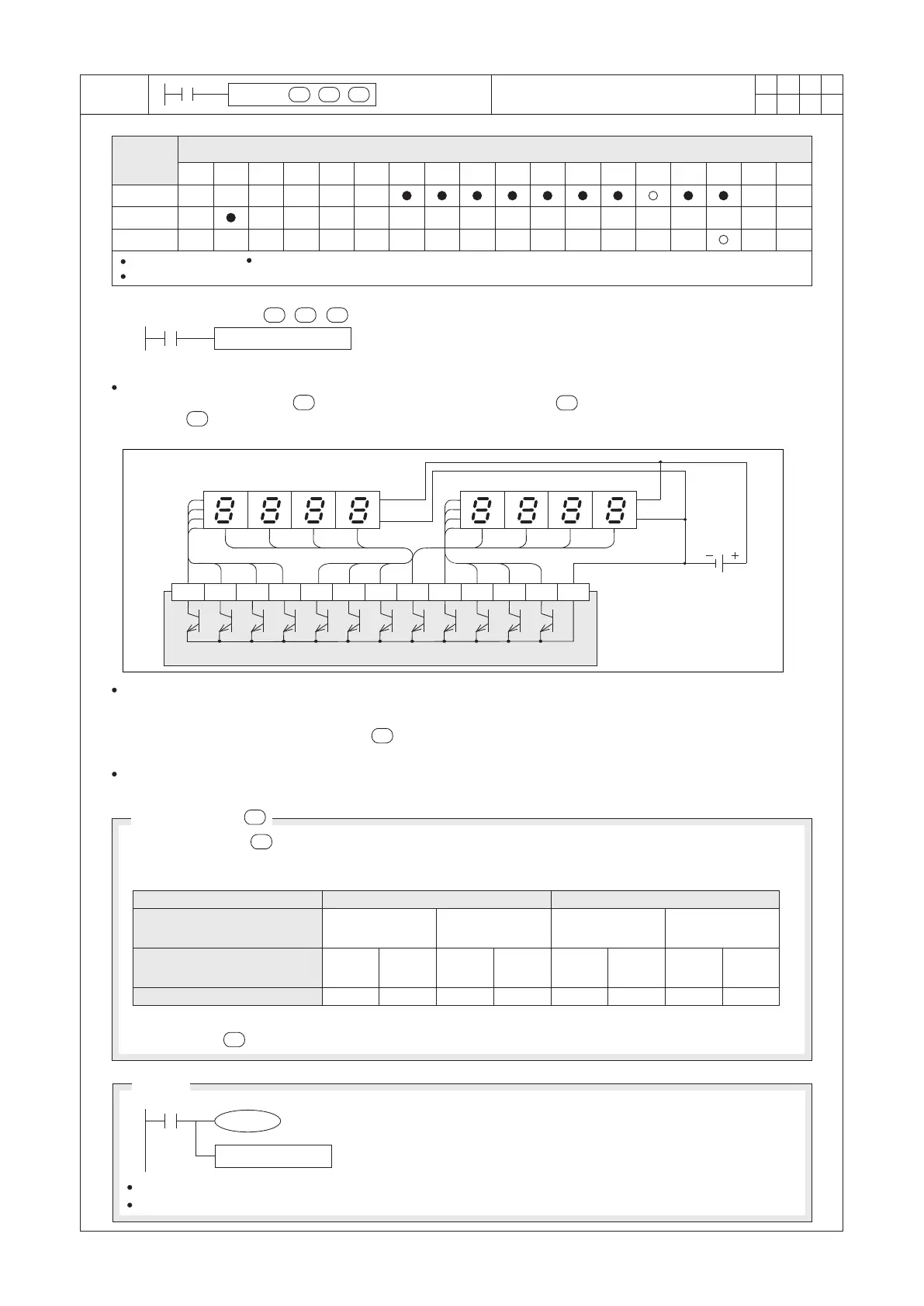
Scan Output Circuit for Seven Segment Display
Display Set #1 ★ Display Set #2 ★
Transistor output points of the PLC
The diagram shown above is the circuits of a seven segment display composed of Y20~Y27. When X20= “ON”,
the instruction will start to be performed. The value of D0 will be converted into a BCD code then transferred and
displayed on the Display Set #1. If the value of D0 exceeds 9,999, an operation error will occur. If Display Set #2
is also connected with the circuit and the value is set properly, the content value of D1 will be demonstrated on
the Display Set #2.
When X20= “ON”, Y24~Y27 will cycle the output scan automatically. It takes 12 PLC's Scan Time for a display
cycle and M9029 will turn “ON” for a PLC's Scan Time when each cycle is completed.
n
Set Value about
A correct setting of value is not only can be used to match the logic polarity of the PLC transistor output
terminal with the input terminal of the seven segment module, but also to demonstrate there is one or two sets
of display to be used.
Number of Display Sets
Polarity of the PLC's output terminal
and the displayer's data input
terminal
Polarity of the PLC output terminal
and the displayer's data input
terminal
One set
Same Same
Different Different
Two sets
Same Same Same Same
Different Different Different Different
The output will relate to the table above. If the displayer's character is unsure, can orderly insert a number
0~3 or 4~7 to until the seven segment display can demonstrate correctly.
Notice
The SEGL instruction can be used once only in the program.
This instruction is only recommended for use with transistor output modules.
When the instruction is performed, each output scan will need 10ms at
least. If the PLC's Scan Time is less than 10ms, please use the constant
Scan Time function to fix the Scan Time at 10ms.
★
The display must have
latch function.
n
 Loading...