246
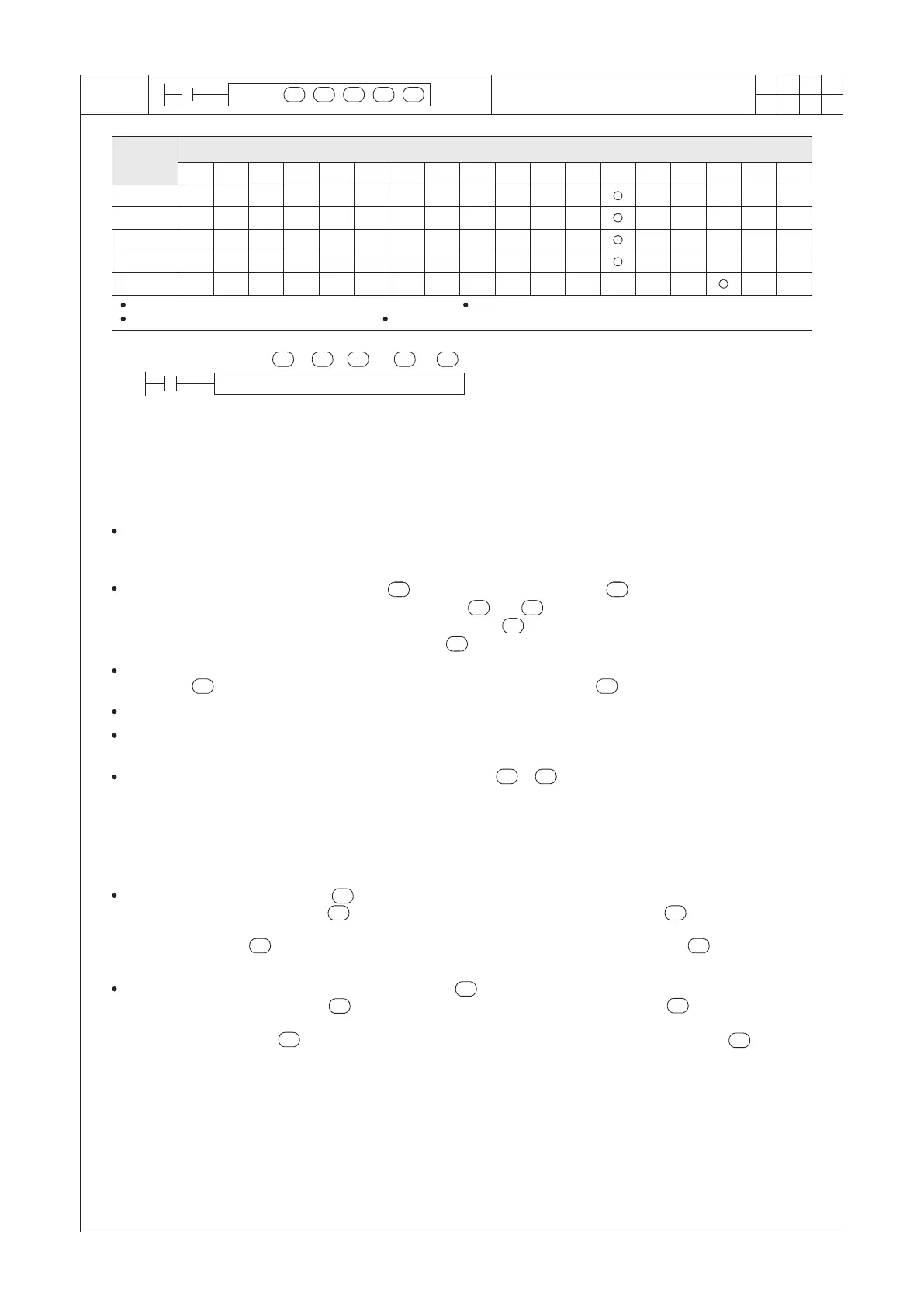
T P D
I
S1
S2 S 3 S 4
n
FNC
92
1
2
M
3
○○○
X Y M S
D.b R.b
KnX KnY
KnM KnS
T C
D,R
V,Z
UnG
K,H
E
" $"
S1
n
S2
S3
S4
X0
TPID D7000 D0 D100 D7100 K16
S1
S2 S3 S 4
n
○
Operand
Devices
Temperature PID Control
S1 and S2 individually occupie n consecutive registers S3 occupies (10×n)+10 consecutive registers
S4 occupies 6×n consecutive registers
n = 1~16
S1 : the initial register ID of the Set Value (SV) block
S2 : the initial register ID of the Present Values (PV)
block
S3 : the initial register ID of the parameters of
instruction & outputs
S4 : the initial register ID of the parameters of PID &
other Set values
n : Number of object channels need to control by
this instruction
This TPID instruction is especially for temperature application at the multi-object (1~16) PID control.
The instruction provides temperature PID control, Auto-Tuning (AT), Auto/Manual control functions and alarms.
So, the instruction can easily procure a smooth temperature control.
The instruction uses the difference between (one in the set value block) and (correlated one in the present
value block), then via the content values of parameters in and to process the PID operate.
The control result signal of coil ON/OFF will effect relative bit at +5. If the analog control output is required, the
result value of PID will appear at correlated register of .
There's no limitation on the times used of the TPID instruction.
This instruction provided with the “Auto-Tuning (AT)” function, it can help users to decide the parameters of P (KP),
I (TI) and D (TD) at the TPID instruction. (Please refer to following pages.)
This instruction accumulates the values of difference between & block at every PLC Scan Time, those with
parameters become parts of operand then effect the control output cycles. So, to use this instruction must pay
attention to the suggestion below:
This TPID instruction allows to be used in a subroutine, interrupted subroutine, step ladder diagram or related to
the conditional jump instruction. However, at the time that the PID instruction is active, must make sure this
instruction can be processed once and only once at every Scan Time. If this instruction has been processed more
than once or had not been executed, that will cause the sampling error or imprecise operation.
The specification of Set Value (SV) block
By the content value of parameter to establish the number of object channels then the block will occupy n
registers.
The content value of is the Set Value (SV) for the first object channel; the content value of +1 is the
Set Value (SV) for the second object channel; and so on.
The specification of the measured Present Values (PV) block
By the content value of parameter to establish the number of object channels then the block will occupy n
registers.
The Present Value (PV) in is from the sensor of the first object channel; the Present Value (PV) in +1 is
from the sensor of the second object channel; and so on.
S2
S1 S2
S1
n
S1
S1 S1
S2
S2
n
When X0= “ON”, this instruction starts to perform; When X0=“OFF”, this process stops and all the output
contacts at +5 will be turned “OFF” also all the analog output values in the will be reseted to “0”.
S3 S3
S2
S2
S3
S3
S4S3
S1

 Loading...